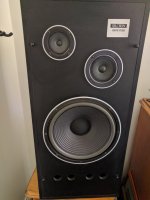
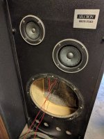
I have a pair of original, Australian made Sansui Silcron Monitor speakers.
Three way, 12" woofer, 5" mid, & 4" tweeter.
Rather than using a dedicated crossover, the tweeters have electrolytic caps in the wiring on the positive wire just before the tweeter + terminal.
They're not cutting edge, but for the right owner they're reasonably dynamic and listenable.
I'm finding they're a little hissy during vocals where "s" is involved
Is it worth experimenting with a resister to control the tweeter and where would I include it in the circuit?
Or, should I re[lace the cap with poly?
Don't want to over capitalise but would love to improve the sound.
Cheers
Attachments
10 days old! How did I miss your latest instalment Cliff? 🙂
A loudspeaker system like this may have its compromises!
I looked at a similar three-way system for another member and found that the mid and tweeter capacitor values were less than optimum.
In order to judge how the frequencies are being divided, I'd like to know the impedance of the mid and tweeter drivers and the value of the capacitor in series with each.
Hi Galu.
Thanks for picking this one up. 🙂
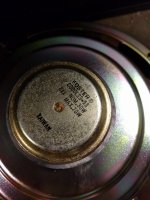
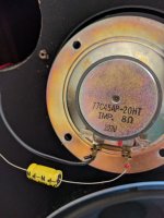
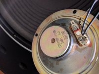
Both Speakers are 8 Ω impedance.
The tweeter has an NPN 100v 2.2μF cap, and the midrange has an NPN 100v 4.7μF cap.
Both caps are wired directly onto their respective drivers.
Hope we can do something with them.
Thanks for picking this one up. 🙂
Both Speakers are 8 Ω impedance.
The tweeter has an NPN 100v 2.2μF cap, and the midrange has an NPN 100v 4.7μF cap.
Both caps are wired directly onto their respective drivers.
Hope we can do something with them.
Attachments
In a properly designed first-order crossover, the mid stops producing high frequencies at the point where the tweeter takes over.
In the existing circuit, the mid doesn't stop, but adds its high frequency contribution to that of the tweeter. The result is likely to be too much high treble accompanied by audible nasties.
In addition, the woofer is not filtered and is adding its unwanted contribution to the mid and higher frequencies.
The only way to deal with this is by using a proper first-order, three-way crossover.
This consists of:
1. A capacitor in series with the tweeter to pass only the high frequencies.
2. A series inductor/capacitor combination in series with the mid to band-pass only the middle frequencies.
3. An inductor in series with the woofer to cut off the mid and high frequencies.
The complete three-way, first-order crossover schematic is shown in the attachment.
Now, we don't know the driver parameters, so have to resort to a crossover calculator and some educated guesswork to arrive at the capacitor and inductor values required to suit your three drivers.
For crossover points of 1,000Hz and 8,000Hz, the required standard capacitor and inductor values would be: C1 = 2.2uF; C2 = 22uF; L1 = 0.2mH; L2 = 1.2mH.
Are you up for the challenge, Cliff!
Attachments
yes, referred to a midrangeC2 = 22u
no, when using a squeaker
Also, Galu, you didn't consider the mechanical crossover
🙂cheerful: but you did break the ice in giving trustworthy answers)
So the same applies to the squeaker, inversely to the woofer (I mean the diameter of the cone radiating similar and in multiples of the frequency/wavelenght to be reproduced) which is used together to the enormous woofer.
Same applies to the treble reproduced by the mid/squeak- a lowpass is always welcomed.
The treble is emitted mostly by the vicinities of the voicecoil, depending on cone stiffness/mass
etc.
😱
Distance between drivers etc. etc
😀
The C can be 2.2<C<10 uF
Can use thinner wire for coil/inductor
probably 1.5 m of 0,5mm enamelled copper, dunno....
(for squeaker)
Can use thinner wire for coil/inductor
probably 1.5 m of 0,5mm enamelled copper, dunno....
(for squeaker)
I'm not sure what you mean by a squeaker. I do know that an alternative name for a midrange is a squawker. 🙂yes, referred to a midrange
no, when using a squeaker
Also, Galu, you didn't consider the mechanical crossover
I did give some consideration to the mechanical crossover of the woofer, but obviously do not have the required data to make a truly informed decision as to the best crossover points. 🙁
I know all of what you talk, but basically I am keeping things simple because of a lack of data and also to aid Cliff's understanding.
"Educated guesswork" was the phrase I used!
Last edited:
I've looked around, and I can't find any other incidence of a tweeter being referred to as a squeaker.
'Squeaker' may be an error of translation.
Woofer, squawker and tweeter - that's the correct usage of terms. 😎
'Squeaker' may be an error of translation.
Woofer, squawker and tweeter - that's the correct usage of terms. 😎
Ooh I didn't see it was Cliff's thread, another one about resurrection & discovering new ways...
Squaker stands for midrange, sure, but in the old way. Nowadays you don't find any Squaker mentioned because it's old
The word itself recalls the sound of the U and the W as the Woof and the Tweet should bring to mind the low and the high frequencies.
Squaker stands for midrange, sure, but in the old way. Nowadays you don't find any Squaker mentioned because it's old
The word itself recalls the sound of the U and the W as the Woof and the Tweet should bring to mind the low and the high frequencies.
 Again
AgainSo I was talking about the usage of the device, the midrange driver, and the limits of the technique. You cannot put a 22 uF in front of low/zero excursion driver (which has closed back, too). The problem in using a real midrange in a properly well designed system is the efficiency (and bandwidth...) and cost: bigger magnet, caps & coils for filtering.
The, "squawker theory" tells that you can rely on the woofer(big) diameter for pistonic behavior and leave the reproduction of the higher notes harmonics to the lesser diameter driver.
The, "squawker theory" tells that you can rely on the woofer(big) diameter for pistonic behavior and leave the reproduction of the higher notes harmonics to the lesser diameter driver.
In a properly designed first-order crossover, the mid stops producing high frequencies at the point where the tweeter takes over.
In the existing circuit, the mid doesn't stop, but adds its high frequency contribution to that of the tweeter. The result is likely to be too much high treble accompanied by audible nasties.
In addition, the woofer is not filtered and is adding its unwanted contribution to the mid and higher frequencies.
The only way to deal with this is by using a proper first-order, three-way crossover.
This consists of:
1. A capacitor in series with the tweeter to pass only the high frequencies.
2. A series inductor/capacitor combination in series with the mid to band-pass only the middle frequencies.
3. An inductor in series with the woofer to cut off the mid and high frequencies.
The complete three-way, first-order crossover schematic is shown in the attachment.
Now, we don't know the driver parameters, so have to resort to a crossover calculator and some educated guesswork to arrive at the capacitor and inductor values required to suit your three drivers.
For crossover points of 1,000Hz and 8,000Hz, the required standard capacitor and inductor values would be: C1 = 2.2uF; C2 = 22uF; L1 = 0.2mH; L2 = 1.2mH.
Are you up for the challenge, Cliff!
With input like this how can I not give it a go.
Thanks for the great detail.
As the Australian made Silcrons were a budget build I need to be careful not to over capitalise.
Is electrolytic OK for the 22uF Caps?
The ones I was looking at are +-10%, 100vdc with non polar axial leads.
For a pair that's $5 instead of $28 on the 22uF caps.
Is 21 AWG OK for the air core Inductors?
Is a circuit board recommended or should I knock one up out of wood or other material?
Thanks
Last edited:
If you read my post carefully, you will see that I am not advocating simply putting a 22uF capacitor on front of the midrange driver!So I was talking about the usage of the device, the midrange driver, and the limits of the technique. You cannot put a 22 uF in front of low/zero excursion driver.
Instead, I am advocating putting a bandpass filter in front of the midrange, which consists of a series combination of a 22uF capacitor and a 0.2mH inductor.
Attachments

So I was talking about the usage of the device, the midrange driver, and the limits of the technique. You cannot put a 22 uF... .
You're cheating me...
😕
HP in my Kentwood 777 was performed by a 22uF and a 1 mH...(if I recall...) LP was 0.1 mH...
Lotsa 10W resistors in the attenuator section before mid&tw sections... Still have the big 15" 🙄
Lotsa 10W resistors in the attenuator section before mid&tw sections... Still have the big 15" 🙄
If you read my post carefully, you will see that I am not advocating simply putting a 22uF capacitor on front of the midrange driver!
Instead, I am advocating putting a bandpass filter in front of the midrange, which consists of a series combination of a 22uF capacitor and a 0.2mH inductor.
Understood. 🙂
My shopping list is:
Pair of Inductors 0.2mH
Pair of Inductors 1.2mH
Pair of Caps 2.2uF
Pair of Caps 22uF
Tweeter use 2.2uF
Midrange use 1.2mH followed by the 22uF Cap.
Woofer use 1.2mH Inductor.
Was just hoping for advice on getting the budget in order, viz, electrolytics for 22uF Caps and whether 21awg is OK for Inductors?
Last edited:
Bipolar electrolytic capacitors are just fine in this application.Is electrolytic OK for the 22uF Caps?
Is 21 AWG OK for the air core Inductors?
There's no need to buy the most expensive inductors in this application. Buy the least expensive ones which are wound with thinner wire.
I hope you also understand that I am making an educated guess in regards to the crossover here. The proof will be in the pudding!Understood. 🙂
My shopping list is:
I can't see the result being worse than what was originally installed though! 🙂
Whatever happens, it will be a useful experience and a further step on the way to you understanding how crossovers work.
Maybe one day you'll progress from 1st order to 2nd order crossovers (as mentioned by picowallspeaker). However, in my opinion, 2nd order would be overkill in your current application.
- Home
- Design & Build
- Construction Tips
- Build time to adjust sound on Sansui Silcron Speakers.