As far as I can see, you still haven't confirmed whether that is due to a faulty left speaker or a faulty left channel of the amplifier.
Swapping the speaker drivers over will reveal the culprit, as I suggested earlier.
OK, finally got around to pulling the second speaker apart and properly testing both drivers.
I must have mis-remembered, because it's clear that it's the RIGHT driver (the one in the same box as the amp) that's misbehaving, not the left. I tested both drivers on both channels, and every time the same driver is about half the volume and much scratchier than the other one. This is actually a surprising improvement, because in the past I could barely even hear it at full volume.
Either way, the drivers obviously need replacing. The board (while cheap and crummy) works.
3.6 litre. Small for a 4”, ideal for some Alpair 6.2m (metal), but A6.2p (paper) could also fit. No need for a tweeter. These are amoungst the very best FR drivers available in this size (an IMO smoke the FE103 [FE103 SOL excluded]).
Both discontinued but d’Archer still has some A6m
Mark Audio 6M
The vent would likely need tweaking, bass resonse anechoic expected to be circa low 60s, F6, low 50s F10. Very good mids and extended top.
You will have to work the box over to come near getting the most out of the drivers. Get the amp good enuff and people will be stunned when you fire them up.
An adaptor may be needed, but the large bezel on these MA Alpairs makes them closer bezel size to common 4”.
https://frugal-phile.com/boxlib/markaudio/A6x-dims.pdf
Exact dimensions of the cutout and the bolt circle (or how far apart in the case of the tweeter).
As to the amp, yours could be toroughly reworked with caps etc, how much could be squezzed out depends alot on the chip under that heat sink. And rework the power supply, that can make for huge benefits. How good a chip amp can be (depending of course on chip) from crappy to really quite good depending on what surrounds it and the implementation. Yours is cheap so compromises on parts supply, everything.
I expect you could get a solid 1-2 w out of it.
The small Class D amps are a very good suggestion. Easiest if you lose the tone controls. I had/have some tiny (really small) Dayton that were surprising good.
If you want to go over the top, a diy preamp specifically designed to purpose driving separate Class A amps outside the box.
Done right one could get a lot of WTF when people come over and listen.
dave
That's a lot of good info, thanks!
Some of the stuff about modifying the vents etc. might be a bit above my head, but I'll keep it in mind.
Now I'm just torn as to whether I should try refurbishing the current board or replacing it with a brand new one. It looks like it might actually work out cheaper to replace the whole board! But staying with the current one would be less work and fiddling/adapting to fit.
Again, what is the size of the bolt circle on the 4”? Hole size? max vert height of the rebate.
The reason i ask is that the rebate is the shape of an FE103. The new one has a bit differetn bezel, but if the dimensions are close a vinatge FE103 might drop right in. If it nominally wants a bit bigger box you can then turn that to your adavatage by damping the port (stuff it with fluff.
dave
The reason i ask is that the rebate is the shape of an FE103. The new one has a bit differetn bezel, but if the dimensions are close a vinatge FE103 might drop right in. If it nominally wants a bit bigger box you can then turn that to your adavatage by damping the port (stuff it with fluff.
dave
Again, what is the size of the bolt circle on the 4”? Hole size? max vert height of the rebate.
The reason i ask is that the rebate is the shape of an FE103. The new one has a bit differetn bezel, but if the dimensions are close a vinatge FE103 might drop right in. If it nominally wants a bit bigger box you can then turn that to your adavatage by damping the port (stuff it with fluff.
dave
Hole size is 104mm (~4.1''). Diagonal distance between the screws is 115mm (~4.5'')
Tweeter hole is 47mm(~1.85''), diag hole distance is 65mm (~2.6'')
peereless TC9 ? 8 ohms... 20 USD
drivers seems 6 ohms ?
Maybe a cleaner picture of the bord to understand,ho it is made , where is the rectifiers, etc...
My multimeter put them at 4 ohms. (Well, 4.5)
Here's some pics of the rectifier (it's separate to the board, attached to the back of the box):


Not sure how better to frame pictures of the board. What should I focus on in particular?
Your multimeter reads the DC Resistance of the driver. It's Nominal Impedance (opposition to AC) is around one third higher i.e. 4.5 + 1.5 = 6 ohm.My multimeter put them at 4 ohms. (Well, 4.5)
Focus on providing a sharp and larger (expandable) version of the attached photo that you posted earlier, which will allow us to see clearly down to individual component level.Not sure how better to frame pictures of the board. What should I focus on in particular?
Attachments
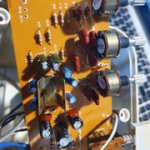
or a 3/4 view to see caps value... the metal thingy is a radiator fo an amplifier ic I surmise...
The red and green caps has to be keeped (film caps). The lytic long can caps are certainly good enough if less 20 years old... however if you see bumped top or leaks at the bases...think tpto a cap refurbishing... Very few thing to improve on the caps side but to avoid a futur refurbishing if you listen everyday... Sometimes some caps have a subjective better snap that can help those mini speakers but it mainly depends of the ic circuitry....
The red and green caps has to be keeped (film caps). The lytic long can caps are certainly good enough if less 20 years old... however if you see bumped top or leaks at the bases...think tpto a cap refurbishing... Very few thing to improve on the caps side but to avoid a futur refurbishing if you listen everyday... Sometimes some caps have a subjective better snap that can help those mini speakers but it mainly depends of the ic circuitry....
Last edited:
Your multimeter reads the DC Resistance of the driver. It's Nominal Impedance (opposition to AC) is around one third higher i.e. 4.5 + 1.5 = 6 ohm.
P.S. The object you are holding is a step-down transformer. The rectifiers are located alongside the other boarded components.
Ah, thanks. Clears a few things up
Focus on providing a sharp and larger (expandable) version of the attached photo that you posted earlier, which will allow us to see clearly down to individual component level.
OK, I've focussed a bit closer, specifically on the caps and labelled them. Are the tantalums of any importance?

The heat sink over the IC, by the way, is soldered on. Really solidly. Just how useful will it be to know what the IC is?
I do not see tantalum.
Oh, I think I meant polyester.
I've tracked down a few drivers on ebay.
4 inch:
4" inch 4Ohm 6Ohm 8Ohm 40W Speaker Woofer Subwoofer Audio Loudspeaker Bass #1 | eBay
2 inch (tweeters):
2pcs 2"inch 8ohm 8Ω 10W tweeter Speaker Neodymium paper cone Loudspeaker | eBay
Do these look like good choices? I'd prefer a source that isn't going to charge me a million dollars to post to Australia.
It's hard to find tweeters of the right dimensions. All I could find were 8ohm ones, but a bit of a google search seems to imply I can get away with this. Can anyone confirm? (Bearing in mind that at the price I don't really care if they add heaps to the sound - I'm half putting them in just for kicks, since there's a hole for them so why not? I just don't want them to make it sound worse.)
yes, the MKT will last more than you and us; keep them.
If the tweeters are working, why changing them ? Just change the falling unit and its cunterpart on the other cabinet.
No idea about the bass unit, Planet10 is the guy to follow for that.
Some rules matter : don't go bellow 6 ohms drivers, choose the wider bandwith in the low end and a low Vas (more or less box volume unit, idealy around 2 liters to 4 liters on the datasheet should work) as a not too high wattage because the little IC to hit the mak level the driver is able to !
And of course choose the driver as P10 said in order to fit on the screw pads and hole to keep it air proof.
look at Monacor. Peereless from Thymphany can be found in Oz shops! You may not have problem to find pc speaker drivers units. The one advised by P10 is of course if music matters and seems to look close as per his experience suggests.
Last edited:
Knowing what the chip is would just let us know the specifications and cabability of the amp, but there's no point in pursuing that any further.
I see no reason to change the electrolytic capacitors, or any other components for that matter.
Can you link the amp up to a spare pair of passive Hi-Fi speakers to gauge how well it performs?
If it performs well, then concentrate on replacing the drivers in the plastic cabinets.
P.S. I've just seen your latest post regarding the drivers you have tracked down.
Last edited:
To clarify - there are currently no working tweeters in the plastic cabinets - just dummy, imitation ones.If the tweeters are working, why changing them ?
Hummmm, why bother ? A full range is what one needs here!
I don't know if this one feets : https://www.parts-express.com/pedocs/specs/264-1062--tymphany-tc9fd18-08-spec-sheet.pdf
less than 10 usd at Part Express
easy to find anywhere on the planet.
btw , curently drinking a 14 yo Tormore")
I don't know if this one feets : https://www.parts-express.com/pedocs/specs/264-1062--tymphany-tc9fd18-08-spec-sheet.pdf
less than 10 usd at Part Express
easy to find anywhere on the planet.
btw , curently drinking a 14 yo Tormore
Last edited:
If the tweeters are working, why changing them ? Just change the falling unit and its cunterpart on the other cabinet.
Because the current tweeters are literally blank hunks of plastic
Yes, that's been my main limiting factor in finding appropriate drivers. There's plenty of 4'' 6ohm speakers out there, but not many with the right shape/size footprint and screw hole locations.And of course choose the driver as P10 said in order to fit on the screw pads and hole to keep it air proof.
8 ohm tweeters will be fine. Include a 2.2uF bipolar series capacitor.
The 4" drivers look reasonable, but you could probably find a suitable one for less outlay.
Yeah, I thought they looked a bit expensive. But so far they're the least dicey looking ones I could find that would fit. I'll keep looking...
Knowing what the chip is would just let us know the specifications and cabability of the amp, but there's no point in pursuing that any further.
I see no reason to change the electrolytic capacitors, or any other components for that matter.
Can you link the amp up to a spare pair of passive Hi-Fi speakers to gauge how well it performs?
If it performs well, then concentrate on replacing the drivers in the plastic cabinets.
OK, to my surprise (and strangely disappointment), I did this and it actually sounded decent... at least to my inexperienced ears. A little bit thin perhaps, but I was just using a unit that's meant to be matched with a sub-woofer.
I was actually sort of looking forward to dropping in some nice audio grade capacitors haha! (But agreed - there's no point if it sounds fine as is)
- Status
- This old topic is closed. If you want to reopen this topic, contact a moderator using the "Report Post" button.
- Home
- Design & Build
- Construction Tips
- Beginner wants help retrofitting old PC speakers