V
Vek
I found this one looking around in this marvellous forum:
sfx did a little BCA style amp some time ago: http://www.diyaudio.com/forums/showthread.php?postid=387348#post387348
The link to his site (with schematic right there):
http://users.rsise.anu.edu.au/~felix/iar/Projects/Thunderball/index.html
It looks really straight forward ... ;-)
Cheers
sfx did a little BCA style amp some time ago: http://www.diyaudio.com/forums/showthread.php?postid=387348#post387348
The link to his site (with schematic right there):
http://users.rsise.anu.edu.au/~felix/iar/Projects/Thunderball/index.html
It looks really straight forward ... ;-)
Cheers
Do you plan to implement "circulating current/overlap/deadtime" control somehow?mrx23 said:
Its way better than ClassD, the FETs have got
separate Drivers with NO deadtime.
The high side fets have got +Vcc+12V driving source from the PSU. There is no need of Bootstrap! And half bridge drivers have dead time, so the are completely wrong for BCA!
Thanks to NO dead time the THD will be very low!!!
Problem with BCA is that idle current circulating between mosfets and coils has to be at least half of peak load current or output voltage is distorted.
(or if you are unlucky you end up with 100A circulating around your output stage and making it HOT)
Check what Gyula says about it :
http://www.diyaudio.com/forums/showthread.php?s=&threadid=69429&highlight=
Look what did I found:
All Crown schematics:
http://www.torrentspy.com/torrent/1068220/Crown_K1_K2_schematic_service_manual_BCA_amplfier
All Crown schematics:
http://www.torrentspy.com/torrent/1068220/Crown_K1_K2_schematic_service_manual_BCA_amplfier
There aren't any viruses in the torrent, it doesnt have any executable files just PDFs and MS9s.
I scanned with the latest NOD32!
And ofcourse dont use InternetExplorer with any torrent sites! Use mozilla or opera.
Open the .torrent file with uTorrent:
http://utorrent.com/download.php
I scanned with the latest NOD32!
And ofcourse dont use InternetExplorer with any torrent sites! Use mozilla or opera.
Open the .torrent file with uTorrent:
http://utorrent.com/download.php
Yes you are right!TOINO said:Everybody could found that schematics on Crown site…
mrx23 said:But not the K1/K2
They are there but the pdf files names are in numeric format not alphabets....Toino knows it very well...
Do you plan to implement "circulating current/overlap/deadtime" control somehow? Problem with BCA is that idle current circulating between mosfets and coils has to be at least half of peak load current or output voltage is distorted. (or if you are unlucky you end up with 100A circulating around your output stage and making it HOT)
Does anyone know how to solve this circulating problem?
Is it possible to do without current feedback?
You can download the K1/K2 schematic+service manual from the official site:
http://www.crownaudio.com/pdf/legacy/k-series_servicemanual-schematics.zip (9MB)
Also check out the CE-4000 amp, almost the same, but there is no feedback at the triangle generation part.
http://www.crownaudio.com/pdf/legacy/CE4000Schematics.pdf
http://www.crownaudio.com/pdf/legacy/130485-1_11-02_ce4servrev-b.pdf
For both type amps you can set a DC offset value in the triangle generator for compensating full cancellation at the output.
The optocouplers can be replaced with 2x6N137 10Mbs.
Here is my simulation result (with integration pre-feedback)
PSU is: +-2.5V Comparators max differential input voltage is 2.1V
http://img264.imageshack.us/img264/7629/wholebcafbcw6.png
Service manual says K series draw <=100W quiescent power! (not very efficient)
After 6esc, 10W in sleep mode.
You can downloaded it, but you MUST delete it after downloading I take no responsibility for it.
The scematics are only for 1 channel!
http://onlany23.atw.hu/Crown Input Board.pdf
http://onlany23.atw.hu/Crown Main Board.pdf
http://onlany23.atw.hu/Crown Output Module.PDF
http://onlany23.atw.hu/Crown K seri...vice Manual.pdf
Sorry. I misunderstand!
Greets:
Tyimo
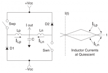
The service manual says:
The current rises at a controlled rate in the Lp and Ln inductors (see the current diagram to the right in Figure 4.1). Halfway through the cycle, the switches turn off
The Lp and Ln inductors control the rate of rise of the current during this time so that this does not act like a short during the couple of microseconds that they are on.
Current Monitor Audio output current levels are monitored by the use of transformer T100. A small primary winding is in series with the output current and the secondary develops a voltage across R140 proportional to the output current of the amplifier. This output current information is used for two purposes: -Negative feedback -Current feedback information for the modulators.
Attachments

- Status
- This old topic is closed. If you want to reopen this topic, contact a moderator using the "Report Post" button.
- Home
- Amplifiers
- Class D
- Redesign Crown K2/1 BCA amplifier (with schematic) pls help with the feedback