Greetings,
My group is going to be building a high power Class D amp for subwoofer apps ( <100Hz)
general questions:
1) Is there a problem with a full bridge desing without feedback?
2) Why do commercial applications that create Class D for subwoofer apps have switching freqs of 50-150Khz? Will 1Khz be acceptable (besides 2x for Nyquist criteria). Are the transistors more efficient if they are being switched rather than conducting? In other words are switching losses < conduction losses?
3) We would like to create a 3-state PWM. Most PWMs have 2 states, ON and OFF. We would like ON, OFF and Idle. This is because for 2-state PWM if the input is zero, then the duty cycle is 50% and the system is incurring losses. Anyone have any ways to implement this? Im sure it has to do with signal conditioning part of the circuit.
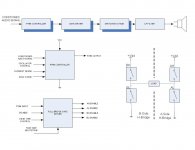
Attached is a block diagram
My group is going to be building a high power Class D amp for subwoofer apps ( <100Hz)
general questions:
1) Is there a problem with a full bridge desing without feedback?
2) Why do commercial applications that create Class D for subwoofer apps have switching freqs of 50-150Khz? Will 1Khz be acceptable (besides 2x for Nyquist criteria). Are the transistors more efficient if they are being switched rather than conducting? In other words are switching losses < conduction losses?
3) We would like to create a 3-state PWM. Most PWMs have 2 states, ON and OFF. We would like ON, OFF and Idle. This is because for 2-state PWM if the input is zero, then the duty cycle is 50% and the system is incurring losses. Anyone have any ways to implement this? Im sure it has to do with signal conditioning part of the circuit.
Attached is a block diagram
Attachments
mcintoda said:My group is going to be building a high power Class D amp for subwoofer apps ( <100Hz)
Based on your questions you would be better off trying to build a low power class d amp - Tripath makes such chips, and there are solutions from other companies out there as well. The cost of such a project will be lower and it will be less complicated.
mcintoda!
(What is "your group"? Your classmates?)
No, if you don't mind high distortion, or you are such an expert like Texas Instrument's designer, who can achieve low distortion even without feedback.
Because
- inductor of filter below 5 kHz cutoff is huge
- < 18kHz is audible.
Actually it should be 3-level PWM, implemented by 4 states.
In 3-level PWM there is 4 state: Positive, Negative, ZeroHigh and ZeroLow! Idle state (high impedance) is unusable in audio amps. ZeroLow is implemented by turning on low side mosfets, ZeroHigh by turning on high side mosfets. During a cycle both Zeros are used alternatedly.
http://users.hszk.bme.hu/~sp215/elektro/eszosztas/3 level PWM.gif
- 2524 is unable to produce 3 level PWM. For 3 level PWM you must have triangle wave instead of sawtooth, and 2 comparator.
- IRFP260N is bad choice. High Rds, high gate charge. Choose a lower voltage, lower resistance, lower gate charge, and faster one!
- Make dead time adjustment!
- Attach a filter!
Is 30V the voltage of the final design?
(What is "your group"? Your classmates?)
Is there a problem with a full bridge desing without feedback?
No, if you don't mind high distortion, or you are such an expert like Texas Instrument's designer, who can achieve low distortion even without feedback.
Why do commercial applications that create Class D for subwoofer apps have switching freqs of 50-150Khz?
Because
- inductor of filter below 5 kHz cutoff is huge
- < 18kHz is audible.
We would like to create a 3-state PWM. Most PWMs have 2 states, ON and OFF. We would like ON, OFF and Idle. This is because for 2-state PWM if the input is zero, then the duty cycle is 50% and the system is incurring losses.
Actually it should be 3-level PWM, implemented by 4 states.
In 3-level PWM there is 4 state: Positive, Negative, ZeroHigh and ZeroLow! Idle state (high impedance) is unusable in audio amps. ZeroLow is implemented by turning on low side mosfets, ZeroHigh by turning on high side mosfets. During a cycle both Zeros are used alternatedly.
http://users.hszk.bme.hu/~sp215/elektro/eszosztas/3 level PWM.gif
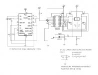
here's the schematic so far
- 2524 is unable to produce 3 level PWM. For 3 level PWM you must have triangle wave instead of sawtooth, and 2 comparator.
- IRFP260N is bad choice. High Rds, high gate charge. Choose a lower voltage, lower resistance, lower gate charge, and faster one!
- Make dead time adjustment!
- Attach a filter!
Is 30V the voltage of the final design?
Thanks for your input!
We are 4 seniors in Electrical Engineering creating class D amp for a project.
Ok, I realize that the inductor size limitations dictate that the switching frequency must be sufficiently high. I will look around for a high-current rating inductor.
I understand your concept of Zero H and Zero L. It seems that, with our full bridge MOSFET controller, I just need to supply the right logic to turn the proper MOSFETS on or off.
The question I have is HOW to create the 4-state (or "3-state") signal from the audio. Do you need 2 comparators for:
1 for comparison w/ audio
1 for comparison w/ inverted audio signal
then some AND logic to get a 3 state signal?
I am having difficulty understanding the picture you attached.
The filter is not shown, you are correct. Furthermore the dead-time is built in with the SG2524 PWM controller or with the gate driver (HIP 4082).
Thanks for you help!
david mcintosh
Just the two comparators. You don't need any more logic.
You must remeber the output is taken as the difference of the two halfbridges. That means that it is indeed 3-state from the view of the load. Here's a table to show what I mean.
Four different inputs produce only three outputs.
You must remeber the output is taken as the difference of the two halfbridges. That means that it is indeed 3-state from the view of the load. Here's a table to show what I mean.
Code:
Out1      Out2     Difference (Out1-Out2)
  0        0              0
  1        0              1
  0        1             -1
  1        1              0
Four different inputs produce only three outputs.
here's an explanation about multi-level class-d
http://bogo-united.oeb.tdk.net/graphics/powerhouse/user_graphics/library/aes_publications/4447.pdf
http://bogo-united.oeb.tdk.net/graphics/powerhouse/user_graphics/library/aes_publications/4447.pdf
- Status
- Not open for further replies.
- Home
- Amplifiers
- Class D
- Full Bridge Class D