Greetings to all:
I am trying to simulate a UcD design in LTSpice. The design goal is to produce a class D that has the UcD discrete front-end and an IC gate driver output stage.
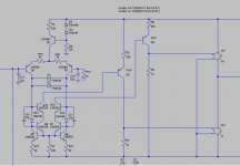
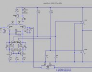
The whole thing is based on a small-ucd design I got here. I made sure that it worked with single-ended input, and then I took out the discrete driver stage and replaced with two lever shifters (to make them reference to the negative rail), and then added two voltage-controlled switches, SH and SL, implemented in two .model statements:
.model SH SW(Vt=0.5 Ron=0.01)
.model SL SW(Vt=0.5 Ron=0.01)
Enclosed is the schematic in LTSpice.
I know that the phase may not be correct but that's secondary for now as I cannot get the model to run. LTSpice says that it cannot find model SW.
Any guidance as to how I can get it running?
BTW, this is over stock LTSpice installation. Thanks.
I am trying to simulate a UcD design in LTSpice. The design goal is to produce a class D that has the UcD discrete front-end and an IC gate driver output stage.
The whole thing is based on a small-ucd design I got here. I made sure that it worked with single-ended input, and then I took out the discrete driver stage and replaced with two lever shifters (to make them reference to the negative rail), and then added two voltage-controlled switches, SH and SL, implemented in two .model statements:
.model SH SW(Vt=0.5 Ron=0.01)
.model SL SW(Vt=0.5 Ron=0.01)
Enclosed is the schematic in LTSpice.
I know that the phase may not be correct but that's secondary for now as I cannot get the model to run. LTSpice says that it cannot find model SW.
Any guidance as to how I can get it running?
BTW, this is over stock LTSpice installation. Thanks.
Attachments
Ah Ha....!
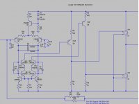
What has happened is that in order for you to get the switches the correct way up you have rotated them 180 degrees and then mirrored them.
In doing that the reference and value designators have swapped over. Both of your switches are still of type SW so you only need one model statement to cover both of them.
.model SW SW(Ron=10m Vt=0.5)
You might want to move the labels so they read
SH
SW
SL
SW
DNA
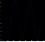
and here is the output:
It as you can tell, has a DC offset to it. the high side is conducting a lot more offen than the low side.
Any cure?
also, the shifters are pretty crude and do not turn on and off as quickly. any suggestions to fix it would be greatly appreciated.
It as you can tell, has a DC offset to it. the high side is conducting a lot more offen than the low side.
Any cure?
also, the shifters are pretty crude and do not turn on and off as quickly. any suggestions to fix it would be greatly appreciated.
Attachments
I think I found a solution.
the DC offset appears to be dependent on the shifter resistor combination. When used a 1k emitter / 2k collector combination, it produced a nice and DC-offset free sine wave.
It appears that it is possible to produce such an amp with UcD front-end, and IC gate driver back end. The advantage of it is the simplicity in house-keeping items (power supplies to the front-end IC in the IRAudAmp for example), high-speed, flexibility and low cost with the discrete solution.
I would still like to fix the level shifters, tho.
also, is it possible to re-arrange the feedback so that the signal is on the non-converting end? I think so.
after playing around with the input signal, the amp seems to have non-flat frequency response curve: the gain is 30x at 1k, 27x at 10k and <25x at 20k, and 12x at 30k.
is that normal?
is that normal?
You don't have anything to turn off your level shifters. Their bases are just driven by the cute stuff at the bottom that can turn them on but then there is nothing to take the charge out afterwards.
I've not studied it but it makes my head hurt. Anyway, try adding some resistors from the bases of your level shifters to the top rail... or figure out a way to add an extra two transistors in the emitters of the originals to turn off the opposite one.
UCD is sort of complicated because Bruno (or the agents) wrote his patent without telling someone not skilled in the art how to do it. Obviously if someone skilled in the art (or not so thick to figure it out) does it then they get stuffed anyway if they end up with a result that looks like what's in the patent.
Mind you..... Bruno might have been lucky..... Yeah, I know... I should go suck prunes. 🙄
That leaves the rest of us guessing at how to do it properly. Like me....... Interesting, time for a play.
DNA

Hi,
Alright, you really only save a house keeping supply by doing this, but given the added complication, as opposed to a few simpleton supplies and a comparator, well, best to say this is a learning experience and leave it at that.
You have to make sure your level shifters dont' saturate of you've messed up. You can also help speed turn off with the use of a base-emitter resistor.
However, hmmmmmmm...... I really think you're overcomplicating this.
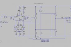
to simplify this, how about this version without level shifters?
the two transistors Q13/14 sink about 3ma each when turned on. so I figured a resistor network would do in driving the two switches on / off.
here it is and let me know what issues you see it having.
the two transistors Q13/14 sink about 3ma each when turned on. so I figured a resistor network would do in driving the two switches on / off.
here it is and let me know what issues you see it having.
Attachments
I don't understand that.....
The original input circuit is some sort of inverse cascode comparator thing that ends up interfacing with the stuff that drives the mosfets so the bottom one ends up being saturated anyway.
If he (sorry Eva, force of habit) turns the circuit upside down (swaps NPNs and PNPs and vice versa) then it all works nice and pretty for driving the IR IC's he wants to use and there are no saturation problems in the 'deviant' comparator thing.
That's what he wanted so.... problem solved. 😕
DNA
the issue of the resistor-based level shifters is that it is picky about the turn-on threshold of the gate driver circuit: as drawn, it would work with ir2011 (Vt=2.2) but not LM5104 (Vt=1.8). I need to play with it a little bit, and then build it.
not sure if I understand you, genometrics. what I wanted is to have a voltage signal referrenced to the negative rail and use that to drive the switches (because I will be using a gate driver ic).
the original circuit is current coupled through q13/q14: it outputs a current signal (sinking about 3ma each leg) and I needed to turn that into a voltage signal. thus my original though of using a level shifter to force the conversion to the negative rail.
also, the emitters of the level shifters can be tied to ground instead of the positive rail.
fokker said:not sure if I understand you, genometrics.
Go on.... Use LTspice with the grabby hand thing for moving stuff.
Select all of the the input stage stuff and rotate it through 180 degrees and then place it back down on the circuit. You have now turned the circuit upside down.
Now change all the NPN transistors for PNP transistors and change all the PNP transistors for NPN transistors.
Q13/Q14 now source current to the negative rail which is where your driver IC is.
DNA
You need to have a good look about your spice model to see what might really be happening. It might be quite frightening.
Classd4sure made that rubbish up by poking around a UCD and then fiddling about with things until it worked. Now he spends his time telling other people how they haven't got it right without telling them how to get it right because he doesn't know himself.
Wot a stiff 😀
DNA
Classd4sure made that rubbish up by poking around a UCD and then fiddling about with things until it worked. Now he spends his time telling other people how they haven't got it right without telling them how to get it right because he doesn't know himself.
Wot a stiff 😀
DNA
- Status
- Not open for further replies.
- Home
- Amplifiers
- Class D
- UcD / LTSpice help