Sander,
Did the amplifier parts ever arrive and if so how are you progressing?
I was looking at the IR reference design and I have a few questions:
The iraudamp1 application note states:
"A self oscillating scheme contains class D switching stage that requires a start-up triggering signal to charge the high side bootstrap capacitor..."
It goes on to describe the circuit that does this.
1. How will your amplifier start-up?
http://www.irf.com/technical-info/refdesigns/iraudamp1.pdf
This is a general question:
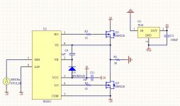
Consider the attachment -- This circuit would never work because the bootstrap capacitor is never able to charge since the source is referenced to GND through the load resistor instead of -26V.
In general the only way the IRF drivers will work with a +/- supply is if both HIN and LIN are driven 180 degrees out of phase.
Or am I mistaken?
Thanks,
-=Randy
Mankato, MN
Attachments
I have another general question:
After taking another look at the schematic I noticed the IR2011 does not implement a soft start pin. During power-up wouldn't this cause turn-on transients that could translate into "thumps" at the speaker and if so could it be eliminated before the IR2011 or would it be better to choose another device from the IRF family such as an IR2110 or IR2113.
Thanks,
-=Randy
Mankato, MN
Hi,
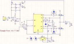
I notice most of the Class D amplifiers I've seen on DIYaudio seem to use some sort of level shifting scheme to get the output of the compartator to "talk to" the input of the mosfet driver. By level shifting the audio input with DC could this be eliminated like shown in my illustration. This is obvious but no one seems to do it so either:
1. I didnt search the forums hard enough
2. Electronically, it's not feasible
In my mind it makes sense to do it this way, and concerning the power supply it would easier. Could someone correct me?
Thanks,
Randy Knutson
Attachments
Alright, got a bit sidetracked and put this project on the backburner for a while. In the meantime I did finish up my UcD400 amplifier that was long overdue. However I have revised and recalculated the class-D amplifier as described here to offer full-range performance and will be getting parts in this week (ordered this afternoon) so I plan to have two prototypes up and running soon and then I'll be sure to see how they fare on the testbench. Here's the updated, latest revision of the schematic and a look at my finished UcD400 amplifier.
SODFA class-D amplifier, revision 007
http://hardwareanalysis.com/images/articles/large/11666.gif
And a few pictures of the (tweaked) UcD400 amplifier featuring the Hypex HG power supply, 300-VA toroids and an assortment of other bits and pieces.


Best regards,
Sander Sassen
http://www.hardwareanalysis.com
SODFA class-D amplifier, revision 007
http://hardwareanalysis.com/images/articles/large/11666.gif
And a few pictures of the (tweaked) UcD400 amplifier featuring the Hypex HG power supply, 300-VA toroids and an assortment of other bits and pieces.
Best regards,
Sander Sassen
http://www.hardwareanalysis.com
To at least try to approach sound quality of the UCDs you may want to allow for balanced inputs, even if you’re not using then right off the bat. It will at last make the project more appealing to others. Upping the input impedance to between 50k – 100k would also be a good idea for people with tube preamps.
You can look at the UCD input stage, published on this site with values, for ideas.
Leve
You can look at the UCD input stage, published on this site with values, for ideas.
Leve
Leve?
The input as described in the schematic is semi-balanced, as is evident from the GND, IN- and IN+ inputs. I don't see the need for a full balanced setup as it would make the design much more complex and since it isn't a full bridge you won't have the full benefit of a differential input as the output stage is still a half bridge. Furthermore input impedance shouldn't exceed ~20K to avoid noise and HF signals to enter at the input stage.
If you make a comment please at least have a understanding of the basic principles of amplifier design, whether class-D or A/AB etc. You've made similar ill informed comments in this thread before that really didn't add to the discussion at all.
Best regards,
Sander Sassen
http://www.hardwareanalysis.com
Alright, couldn't help myself for wanting to simplfy things ever further and have the feedback after the LC filter. I came up with the following schematic, see url below, after some further thinking. In the meantime I've also built a prototype following this schematic which just needs a final checkup (tomorrow) before I flip the power switch.
Semi-discrete Class-D half-bridge (ver. 008)
http://hardwareanalysis.com/images/articles/large/11667.gif


Best regards,
Sander Sassen
http://www.hardwareanalysis.com
Semi-discrete Class-D half-bridge (ver. 008)
http://hardwareanalysis.com/images/articles/large/11667.gif
Best regards,
Sander Sassen
http://www.hardwareanalysis.com
Hi Sanders.
Do you find the common mode chokes on the rails necessary, have they made a difference? Looks very nice.
Now for the homebrew, seems you've done an excellent job of it, very clean, smart layout for the output stage, I like it.
Have you listened to it at all? Looking forward to more.
Regards,
Chris
Do you find the common mode chokes on the rails necessary, have they made a difference? Looks very nice.
Now for the homebrew, seems you've done an excellent job of it, very clean, smart layout for the output stage, I like it.
Have you listened to it at all? Looking forward to more.
Regards,
Chris
Thanks Pierre, Chris,
I had it running for a bit this morning but for some reason the top (V+) MOSFET quit on me and the replacement also. I don't know what happened, but I'm retracing the layout to see whether I might've made a mistake, and am also replacing the IR2011, as that could be faulty. When it did play it sounded somewhat distorted, but it did amplify.
Any suggestions are most welcome,
Best regards,
Sander Sassen
http://www.hardwareanalysis.com
Alright, I'm back to the latest version of the SODFA class-D (ver. 007) as for some reason the simplified version just refuses to work. It does run, but clips against V+ and then burns out the MOSFET and sounds rather distorted all together.
The SODFA however is a different beast, from the moment I turned it on it plays without any audible distortion or other odd behaviour, no hiss or crackles even with my ear physically touching the hexagrid grill that protects my speaker's tweeter.
I'm off doing some measurements with the oscilloscoop and a function generator to see how she holds up. I've been playing through Michael Jackson's Thriller album for the past hour or so and the heatsink is slightly warm at full throttle, the output coil is luke-warm at best. Here's an action-shot of the prototype running MJ's Thriller album")

Best regards,
Sander Sassen
http://www.hardwareanalysis.com
The SODFA however is a different beast, from the moment I turned it on it plays without any audible distortion or other odd behaviour, no hiss or crackles even with my ear physically touching the hexagrid grill that protects my speaker's tweeter.
I'm off doing some measurements with the oscilloscoop and a function generator to see how she holds up. I've been playing through Michael Jackson's Thriller album for the past hour or so and the heatsink is slightly warm at full throttle, the output coil is luke-warm at best. Here's an action-shot of the prototype running MJ's Thriller album
Best regards,
Sander Sassen
http://www.hardwareanalysis.com
(off topic)
Cleanest UcD400 implementation I saw so far. A few questions:
* You're using pots for volume control, which did you use?
* DC protection signal is a very thin wire - I wonder how much current could travel along this wire? I used 1.5mm², probably one of my bad ideas...
* 300VA/40.000uF per channel... wow.
* I see from the daughterboard on the UcD400 that you are using the latest version - I've tried to look in the UcD400 thread to see if this version has the DC blocking caps before or after the opamp - do you know?
Edit: Not the same UcD I have - mine has a red "rounded" output cap instead of a "white block"
Thanks & enjoy the amp
And a few pictures of the (tweaked) UcD400 amplifier featuring the Hypex HG power supply, 300-VA toroids and an assortment of other bits and pieces.
Cleanest UcD400 implementation I saw so far. A few questions:
* You're using pots for volume control, which did you use?
* DC protection signal is a very thin wire - I wonder how much current could travel along this wire? I used 1.5mm², probably one of my bad ideas...
* 300VA/40.000uF per channel... wow.
* I see from the daughterboard on the UcD400 that you are using the latest version - I've tried to look in the UcD400 thread to see if this version has the DC blocking caps before or after the opamp - do you know?
Edit: Not the same UcD I have - mine has a red "rounded" output cap instead of a "white block"
Thanks & enjoy the amp
Yves,
I was about to send you a PM or an email (in Dutch, since I'm Dutch) but you have both features disabled, so I'll also go off-topic for a bit:
* You're using pots for volume control, which did you use?
These are Vishay PE30's, Farnell as well as RS Components carry them, 3-watts Cermet. I picked these after ordering all the pots both these distributors stock and evaluating every single one of them, these 'sounded' most neutral, ie. you can't hear them.
* DC protection signal is a very thin wire - I wonder how much current could travel along this wire? I used 1.5mm², probably one of my bad ideas...
There's no current going through that wire, it is just meant to interface with the DC protection on the PSU, if it senses a DC voltage > +/- 7-volts it'll engage the relays and disconnect the PSU.
* 300VA/40.000uF per channel... wow.
Dual mono is the way to go, esp. with class-D, due to power-supplu pumping and cross-talk issues. There's also the risk of modulating the other class-D amp on the same PSU, so don't go that route.
* I see from the daughterboard on the UcD400 that you are using the latest version - I've tried to look in the UcD400 thread to see if this version has the DC blocking caps before or after the opamp - do you know?
It has them before the opamp, I actually removed them (this amp is DC-coupled) due to the fact that it uses the AD8620 which has virtually nil offset voltage.
Best regards,
Sander Sassen
http://www.hardwareanalysis.com
Edit: spelling and grammar, can't stand sloppy writing.
Pierre said:Sorry, but I really can't found the chokes in the rails you refer to, Chris.
Good layout, Sander.
How does it sound, and what power do you expect from it?
Good work,
Pierre
Hi Pierre, follow the blue/white wires from the supply, to a little donut that they loop through.
UCD400 and UCD180 are both supposed to have caps back after the op amp these days.
Mono blocks are the way to go of course but you sure can get excellent sound from a stereo config. Pumping is a complete non issue but you can invert one phase as welll.
Sanders it sounds like for some reason it clipped hard as you say and perhaps the bootstrap cap ran out of steam and dropped the gate voltage to the point it smoked. Use a much bigger bootstrap cap so it can hold the gate high for a longer period of time. Why it clipped like that in the first place, I can't help ya there.
Regards,
Chris
Chris,
Ah, you meant the toroids in the UcD, I was confused as I did not use any toriods (other than the output coil) in the design discussed here. I actually put those in the UcD400 amp to electrically seperate the two compartments. The steel seperator pictured acts to devide the case into two compartments. Due to the toriods less HF garbage gets into the PSU section and vice-versa.
But going back to the amp discussed here, I just looked at the carrier frequency on the scope and it is a bit on the high side, 770KHz, as well as having a fair amount of spiking at the crossover, have a look below. Comments are most welcome as always, as I'm not sure how to intepret the image exactly. If you have any suggestions on how to do a THD measurement I'm all ears as well, would the RightMark AudioAnalyzer work? And how to set that up?

Best regards,
Sander Sassen
http://www.hardwareanalysis.com
Ah, you meant the toroids in the UcD, I was confused as I did not use any toriods (other than the output coil) in the design discussed here. I actually put those in the UcD400 amp to electrically seperate the two compartments. The steel seperator pictured acts to devide the case into two compartments. Due to the toriods less HF garbage gets into the PSU section and vice-versa.
But going back to the amp discussed here, I just looked at the carrier frequency on the scope and it is a bit on the high side, 770KHz, as well as having a fair amount of spiking at the crossover, have a look below. Comments are most welcome as always, as I'm not sure how to intepret the image exactly. If you have any suggestions on how to do a THD measurement I'm all ears as well, would the RightMark AudioAnalyzer work? And how to set that up?
Best regards,
Sander Sassen
http://www.hardwareanalysis.com
Chris,
I think it is some switching issue, since I'm clocked at about 350KHz faster than the UcD I'm comparing to. For reference please see the same image of the UcD below, it has very minimal spiking. This again is with the input muted and the scope attached across the speaker terminals, carrier frequency of the UcD is 400KHz. I'll go ahead and lower the carrier frequency and see whether that changes things somewhat

Best regards,
Sander Sassen
http://www.hardwareanalysis.com
I think it is some switching issue, since I'm clocked at about 350KHz faster than the UcD I'm comparing to. For reference please see the same image of the UcD below, it has very minimal spiking. This again is with the input muted and the scope attached across the speaker terminals, carrier frequency of the UcD is 400KHz. I'll go ahead and lower the carrier frequency and see whether that changes things somewhat
Best regards,
Sander Sassen
http://www.hardwareanalysis.com
- Status
- This old topic is closed. If you want to reopen this topic, contact a moderator using the "Report Post" button.
- Home
- Amplifiers
- Class D
- My NON-discrete SODFA class-D amp