output cap on lm317 is there but a little distant next to opamps, lm317 doesn't really deteriorate here without outputcap btw inputcaps are rubycons and now those bypasses plus the blue one, noise reduction would be a cap parallel to the 3k6 resistor 10-22uF
from post #552
i try something
actually the amp 2 with the white PCB =V5 is corrected at the LM317 for using 24V input and 20,3V at the output.
i did solder the same caps as discribed before.....page 53 #521
and additionally with a 10µF elco cap at Cadj (parrallel to the R2 =3581ohms)
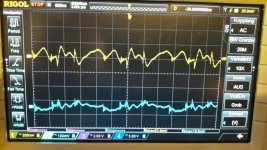
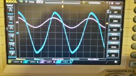
yellow is at input
blue is at the output of the LM317
pic 1 LM317 noise_without 10uF at Cadj
pic 1 LM317 noise_with 10uF at Cadj
no big difference at the output. = 18,8mV - 18,2mV
but a difference at the input about 82mV - 48mV (watch out the settings on the scope is at the input different)
so i guess its working fine = according to the data sheet.
20V out and its 18mV noise so its not 0,003%Vout. its better 0,001 %Vout
Attachments
V5 White pcb clipping measurements
Hi
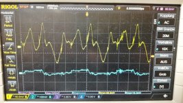
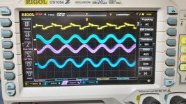
now i looked at the frequency and the clipping with the scope. the sinus wave starts about 6kHz to scatter a little bit.
all test are with 8 ohms lad and 1Vrms at the inputs. regular 24V psu. lm317 set to 20V. so no clipping because under 20V")
pic 1 8kHZ starts to scatter...no nice sinus wave form
pic 2 16kHz
pic 3 20kHz
next is sound check....both amps 20V LM317 set and both LM49720......
Hi
now i looked at the frequency and the clipping with the scope. the sinus wave starts about 6kHz to scatter a little bit.
all test are with 8 ohms lad and 1Vrms at the inputs. regular 24V psu. lm317 set to 20V. so no clipping because under 20V
pic 1 8kHZ starts to scatter...no nice sinus wave form
pic 2 16kHz
pic 3 20kHz
next is sound check....both amps 20V LM317 set and both LM49720......
Attachments
Is this measured at the amps outputs?
I wonder if the scaling is correct. 12.5Vpp is just 10W into 8R. Have you checked the signal at the LM49720 outputs?
Hi Doctor
Yes this is measured at the output socket. its drawing about 1.2x Amps so its little bit more Watt.... but...
no i didn´t check the signal at the op amps. How should i proceed.........mybe tomorrow?
other measurments ok? in your opinion?
chris
You should measure the signal out of the opamp to make sure it's the TPA/output filter which is forming the some wave. Do you measure fully differential at the output? Otherwise the readings are wrong.
The 1.2A can be ground current if you connect a single ended signal to GND and the amps outputs at the same time to the scope if it's not isolated or measured with a differential probe.
The 1.2A can be ground current if you connect a single ended signal to GND and the amps outputs at the same time to the scope if it's not isolated or measured with a differential probe.
Last edited:
V3 with 10µF at Cadj...
Hi
i soldered the 10µ electrolytic cap in the blue pcb (v3)
same procedure at post #561
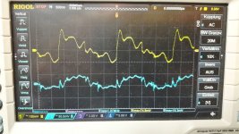
so pic 1 is without
pic 2 is with 10µF at C adjust
i wonder that the input noise is at both cases more then at the other amp and the output is lower with cap at Cadj = 13,6mV
before i start a realize a difference of V3 and V5. At the v5 (white) you can see the volatges at LM317 IN and OUT on the scope without power on the amp. the psu is socket in but amp is off.
at v3 version
I can connect the psu but i can see about 2 volts at LM317 out. if I switch on I can look at the ramp up of the volateges, =24V and 20,2Volt...
if you switch off you can see the voltages falling down.
Hi
i soldered the 10µ electrolytic cap in the blue pcb (v3)
same procedure at post #561
so pic 1 is without
pic 2 is with 10µF at C adjust
i wonder that the input noise is at both cases more then at the other amp and the output is lower with cap at Cadj = 13,6mV
before i start a realize a difference of V3 and V5. At the v5 (white) you can see the volatges at LM317 IN and OUT on the scope without power on the amp. the psu is socket in but amp is off.
at v3 version
I can connect the psu but i can see about 2 volts at LM317 out. if I switch on I can look at the ramp up of the volateges, =24V and 20,2Volt...
if you switch off you can see the voltages falling down.
Attachments
You should measure the signal out of the opamp to make sure it's the TPA/output filter which is forming the some wave. Do you measure fully differential at the output? Otherwise the readings are wrong.
The 1.2A can be ground current if you connect a single ended signal to GND and the amps outputs at the same time to the scope if it's not isolated or measured with a differential probe.
to 1st
the psu is full isolated and has no conector to earth.
the socket of the psu is GND and is not Earth ground. i just connect the scope probes there as GND for all channels and to the + at output L
noob error
???to 2nd
i measured the amps with my DMM at the output at channel R, at channel L i measure the Volatege with scope. so i can see if one channel switched off...
thanks
chris
..sound check without/with 10µF at Cadj LM317
Hi again
last for tonight..
i checked several times the amp without Cadj vs amp with Cadj.
my impression is that the amp with this 10µ is soundding with more darkness in the background and the sound is stable between the speakers and not flodding to my seat. its a smal difference but its repricable.
chris
noise on the right channel _v3 blue...?
Hello
after long period change to new laptop i am back again.
i realized on the amp v3 (blue) a noise on the R - channel. i checked with changing left and right speakers and it keeps on the right channel of the amp. its noisy and i can hear it from my seat about 2,90m away a "pink noise" !!!
with or without source on the inputs its the right channel.
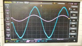
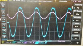
i did a measurement with RCA shorted-
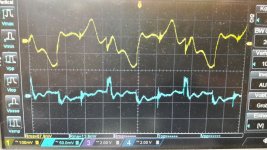
from top to buttom...
yellow channel 1 is RCA connection
blue and pink are the signals on R Channel OUT + and Out -
dark blue is the L-Channel Out +
this measurement did not help me.
additionally i checked with 1khz rca input all of the op amps outs and it looks "normal"
what should i check??
soldering , caps......
thanks
chris
Hello
after long period change to new laptop
i am back again.i realized on the amp v3 (blue) a noise on the R - channel. i checked with changing left and right speakers and it keeps on the right channel of the amp. its noisy and i can hear it from my seat about 2,90m away a "pink noise" !!!
with or without source on the inputs its the right channel.
i did a measurement with RCA shorted-
from top to buttom...
yellow channel 1 is RCA connection
blue and pink are the signals on R Channel OUT + and Out -
dark blue is the L-Channel Out +
this measurement did not help me.
additionally i checked with 1khz rca input all of the op amps outs and it looks "normal"
what should i check??
soldering , caps......
thanks
chris
Attachments
Hi Chris,
Is it an FX502 (TDA7498) or an FX502SPRO (TPA3250) that gives you problems? I have noticed you have more of them.
Can you recall if the amplifier was silent before you started the modifications?
A proposal to check if it is the power amplifier itself that causes the noise or an OPAMP: Use a test speaker, for hearing noise you do not need your good speakers.
An 8 Ohm dummy load connected to the two (normal) speaker terminals of the flawed channel. A speaker (8 Ohm) connected to only one of the speaker terminals, the other end of the speaker being connected to '+" on a 1000uF or 2200uF capacitor. The negative terminal (-) of the capacitor being connected to amplifier ground. No signal at the input.
The normal output is two amplifiers operating in counter-phase. What we would like to know is if it is only one of the two amplifiers that introduces the noise.
If only one of the two amplifiers of the noisy channel has noise, it is unlikely the noise is introduced by an OPAMP. We can then concentrate on the power amplifier itself. If both speaker terminals have noise, it is likely the noise comes from the amplifier input with an OPAMP as the source.
Your ears are vey sensitive to noise. The noise may be there even if you cannot see the noise with an oscilloscope.
Last edited:
Hi Chris,
Is it an FX502 (TDA7498) or an FX502SPRO (TPA3250) that gives you problems? I have noticed you have more of them.
Can you recall if the amplifier was silent before you started the modifications?
A proposal to check if it is the power amplifier itself that causes the noise or an OPAMP: Use a test speaker, for hearing noise you do not need your good speakers.
An 8 Ohm dummy load connected to the two (normal) speaker terminals of the flawed channel. A speaker (8 Ohm) connected to only one of the speaker terminals, the other end of the speaker being connected to '+" on a 1000uF or 2200uF capacitor. The negative terminal (-) of the capacitor being connected to amplifier ground. No signal at the input.
The normal output is two amplifiers operating in counter-phase. What we would like to know is if it is only one of the two amplifiers that introduces the noise.
If only one of the two amplifiers of the noisy channel has noise, it is unlikely the noise is introduced by an OPAMP. We can then concentrate on the power amplifier itself. If both speaker terminals have noise, it is likely the noise comes from the amplifier input with an OPAMP as the source.
Your ears are vey sensitive to noise. The noise may be there even if you cannot see the noise with an oscilloscope.
thanks Fauxfrench
its a FX502Spro. i cannot say if its starting after the modifications. the old notebook as a quite loud fan the last weeks so i have always a small noise floor...that and the damaged display was the reason to change my laptop.
after a scope measuremnt a had a small accident...if forgot to disconnect the psu and i remove the scope probes to sleazy....so i get a short at the LM 317 area...
the LM 317 was still working 20,03V as set before...
i resolder the output terminals and the coils and caps near this area without success. i de solder all modifications on LM 317 and checked all components.
every thing is correct.
i will do so as your proposal...thanks..
..problem solved...!
Thanks to Fauxfrench
i checked with the Speaker and the cap and both Terminals of the R-channel have the same noise.
i changed the right channel op amp to a new one ...and the noise is gone.
to be sure i put the "bad" opamp to the good (i checked this too) L-channel opamp (its closed to the volume knob) and its the same noise.
i guess this "bad" opamp gets punished from my shortcut...
Actually its connect to my normal listening speakers and its fine = no noise on each channel...
thanks
Well done, logical thinking and systematic procedure.
you are my teacher
...new opamp 4562...sound check
Hi
After implementation in one amp i compare:
amp 1 (v3blue) with LM49720
amp 2 (v5 white) with LM4562
i read a lot of post in different forums, all said that this opamaps are the same....
nevertheless.....sound is different and actually i like the sound of LM4562 more:
What is better?
the the dynamic is better, the high are slightly more polished but not oversized.
what i really like is the little better punchy bass (Ultimatum, interpret Disclosure+Fatoumata Diawara, Album Ultimatum) and more sexy saxophones with the LM 4562. (title summertime, interpret tok tok tok, album Gershwin with Strings)
room:
behind the speakers i get cleaner room..so it feels that your seat is 1-2 rows nearer without destroyed arrangement in the middle.
i did the changes at the amp 1 too. so both are playing now with LM4562. actually the amps are the same,that means i am not able to hear a difference between v3 and v5.
chris
Hi irribeo
hopefully the blue (v3) and the white (v5) are the same. i measured the free amp. = no modding , the origianl one white pcb ...
tool = LCR Peakteck 2170
10,5µH
10,7µH
11,2µH
10,9µH
thx
chris
hi shrek7
here it comes... page 54.
i am a noob...coilcraft and Würth should be fine...i read...but maybe one of the developers and expert knows more...
there is not much space to handle with bigger coils...
my intention is not to pimp this amp with more extra budget. my modify is still finished.
cost of the amp with psu is 65 euro
mods are about 8 euros (2 x opamp + lm317 modification +wima at the "big" decoupling caps...
but please share your pics and mods with us.
chris
Last edited:
coilcraft and Würth should be fine
It's not Coilcraft and Wuerth in general but must match a specific modell. There're alot inductors from this two vendors which really aren't doing well as an class-d "filter-inductor".
hi shrek7
here it comes... page 54.
i am a noob...coilcraft and Würth should be fine...i read...but maybe one of the developers and expert knows more...
there is not much space to handle with bigger coils...
my intention is not to pimp this amp with more extra budget. my modify is still finished.
cost of the amp with psu is 65 euro
mods are about 8 euros (2 x opamp + lm317 modification +wima at the "big" decoupling caps...
but please share your pics and mods with us.
chris
Thank you for sharing the values of the air coil conductors, I noticed that most of the Class D amps with this type of conductors have low impact bass, thats is why I want to replace mine with better conductors. coilcraft and wuerth are good brands.
It's not Coilcraft and Wuerth in general but must match a specific modell. There're alot inductors from this two vendors which really aren't doing well as an class-d "filter-inductor".
Hi Doctormord,
would you mind sharing with us specific model of coilcraft inductors which you are using for your projects. or any wuerth coil inductors which can fit this FX amp. TIA
Last edited:
- Home
- Amplifiers
- Class D
- TPA3250 somebody is listening?