I'm amazed no thread comes up under search for iraud200
I'm going to add an iraud200 vs iraud350 rant
Just ordered 2 of these, first one showed up, and it's bothering me a little. But before I get to that, let me put in a positive vote for the iraud200 design .. don't let the iraud350 boards fool you with the larger number (350)... the iraud350 units do not come with irfb4227 transistors, which are the real mosfet powerhouses. The output inductor of the iraud200 is about double the volume of the iraud350 The 200 has also about 15% more heat sink than the 350 .. The iraud200 is the real 2 ohm load driver .. the iraud350 ads often claim it, but but the boards don't really have the hardware installed for 2 ohm loads. I ordered the 350s thinking they were right but didn't know about the little differences that are big differences. It was a very disappointing experience to be fooled in that way. Don't get me wrong, I think there is a very small number of iraud350 boards out there with irfb4227 on board, but they are hard to find, and I still doubt that they have the output inductor installed to match the one on the iraud200. If you want the real deal, you want the iraud200.
the 4227 ohms out in on state at 1/20 of an ohm .. like it's hardly even there. Its rated for around 40 amps current at room temperatures. You want your class D boards to be sporting this transistor. It's the real deal.
The 200 has less capacitance on board by far than the iraud350 ... only plus side for the 350, but it may be less of a plus than you think Having huge capacitance on board means you can't protect the traces from exploding on transistor short circuit. In my opinion, its better to have the caps off board and fuses to protect your traces from major discharge in case of problems.
Both boards use a lot of surface mount components, which is probably good because I remember looking at a through hole board thinking ... how do those through hole components get along with a ground plane because the current flow can't get close enough to the board surface to capacitatively connect to the ground plane properly. However .. replacing surface mount components can be tricky if you have to do that.
The iraud200 appears to have no overcurrent protection. I can not find any hint of overcurrent protection on any spec sheets, though overtemp protection is mentioned. This does not surprise me because I have seen the irs2092 overcurrent protection utterly misbehave. Eliminating it entirely was my final solution .. Don't get me wrong, the irs2092 overcurrent protection logic probably works fine under circumstances .. usually 8 ohm load kinds of circumstance. This means you better have fuses installed for this board, or something better. Fortunately, the dang irfb4227 can handle so ***** much current that the only likely overcurrent event would be trying to drive a one ohm load or a short. This board should handle 21 amps of output current. Not kidding, but I wouldn't push my luck with that. I wouldn't ask it to deliver more than about 600 watts rms into 2 ohms. that's around 17.4 amps .. And that with extra heat sink .. the way I solved that is I just mounted flat surface of a larger heat sink to the top of their heat sink.
I thought the transistor looking thing on the left would be a fet driver .. NOPE, it's a thermostat, so the board does have over temperature protection (yay) and there's where my concerns start. I thought the part to the left of the heat sink was driving the high gate charge of the irfb4227, but no, it appears that the irs2092 is driving the irfb4227s directly as there is nothing on the board that looks like a gate driver (with no gate resistance .. this is a requirement for the high gate charge transistors) . Frankly, that is scary, and it tells me that this board may be designed to poop on you. The iraud350 version direct drives its transistors as well, but a: the transistors have about 30% less gate charge than the irfb4227 (and about double the on-resistance as well as almost double the thermal resistance) and b: the iraud350 boards I got had large heat sinks (over an inch tall) mounted to the irs2092 chip. and c:Those heat sinks got hot. In my opinion, the only way they could direct drive without a heat sink is to do something in the circuit to slow down the firing rate of the transistors .. i.e. slow down the feedback loop. This would a:help to relieve the gate charge problem and b:create a new problem of damage to the sound quality .. I may report on this later.
OK, so looking at the boards, I'm saying to myself I really like the big output inductor, That thing is quite convincing. but ...... I don't want to even charge up the boards without getting heat sinks mounted to the irs2092 chips. To me, that's just irresponsible .. please, anyone with understanding I am missing, let me know, but my exp. thus far says that the irs2092 is not designed for that. Now, just for fun, I found some suitable heat sinks on ebay .. 10 x 35 x 10 mm. They are tall, and deal with it because this chip needs help driving those transistors. And you will need heat sink glue to glue them on. Because I plan on driving 2 ohm loads, I am also going to supplement the regular heat sink and also heat sink the output inductor. .. and of course .. fuse the unit in case of accidental shorting of the output.
Now, just for extras ... I installed irfb4227 transistors on an iraud350, and it worked with no immediate disasters. However, I think the switching of the transistors was not optimal, and the switching losses were high. The heat sink got hot even with no signal, and I had to supplement it. After watching it drive my 2 ohm sub-woofer flawlessly for some months (though without really putting the pedal to the medal cause that's quite noisy you know) .. This driver is a 600 watt (rms) 15 inch subwoofer from MA audio.. dual 4 ohm voice coils wired in parallel (btw .. never just straight out believe your multimeter about the impedence of speakers because they have reactance, not just resistance) ... really big double stacked magnets and at least an inch of xmax in both directions, around 90-91 db efficiency is my best guess, mounted in a 12 foot long bass horn tuned for 20 hz quarter wave, so horn loaded, which means extra air impedance resisting the drivers movement. This board with the 4227 transistors kicked that driver so hard that it bottomed out and banged very audibly... The transistors just smiled at me and said ... fun ... do it again.") I can't imagine doing that with less than 20 amps of current. The power supply is 70 volts with 22000 uf/pole, so up to something more like 30 amps of current and 1800 watts would have been available for transients, which is probably not far from what happend. I'm going to guess 25 amps and 1250 watts transient. The pre-amp stage (not this board) was having issues that created transient jolts (solved since then). This board kicked the driver like that many times and showed no sign of weakness. Of course, its the IRFB4227 transistors that are doing the work. OMG those little transistors are amazing. That kind of jolt would instantly trash the outputs of many amplifiers. I saw it happen for example with a pioneer sx 1050 and only 4 ohm loads ... this was a 2 ohm load!!!
I can't imagine doing that with less than 20 amps of current. The power supply is 70 volts with 22000 uf/pole, so up to something more like 30 amps of current and 1800 watts would have been available for transients, which is probably not far from what happend. I'm going to guess 25 amps and 1250 watts transient. The pre-amp stage (not this board) was having issues that created transient jolts (solved since then). This board kicked the driver like that many times and showed no sign of weakness. Of course, its the IRFB4227 transistors that are doing the work. OMG those little transistors are amazing. That kind of jolt would instantly trash the outputs of many amplifiers. I saw it happen for example with a pioneer sx 1050 and only 4 ohm loads ... this was a 2 ohm load!!!
So, I was hoping for some prior experience with this board to show up, but no luck that I could find. anyone else willing to banter about this board, please drop a line, as I am going to be placing some small bets on this board. I am going to supplement an old pioneer sx-1250 monster receiver with two of them. It is suggested to have separate ground lines for this (to eliminate mutual interference), which I can't do on the 1250 even though it has separate supplies, so I have ordered some ferrite beads and will probably use some inductors as well to quell hf across the ground line. I'll probably report later on how well this "power supply decoupling" works. I remember I had two L-25D boards that just couldn't get along with each other without a struggle.
In any case, despite the heat sink issue, I am seriously rooting for the iraud200 as the cheapest, genuinely 2 ohm capable board for 60-80v power supply poles. ... Oh, and I'm seriously considering putting a really big heat sink on the 1250's transformer as well as maybe also some heat sink on the rectifier diodes, cause I'm going to need another 300 watts.
I'm going to add an iraud200 vs iraud350 rant
Just ordered 2 of these, first one showed up, and it's bothering me a little. But before I get to that, let me put in a positive vote for the iraud200 design .. don't let the iraud350 boards fool you with the larger number (350)... the iraud350 units do not come with irfb4227 transistors, which are the real mosfet powerhouses. The output inductor of the iraud200 is about double the volume of the iraud350 The 200 has also about 15% more heat sink than the 350 .. The iraud200 is the real 2 ohm load driver .. the iraud350 ads often claim it, but but the boards don't really have the hardware installed for 2 ohm loads. I ordered the 350s thinking they were right but didn't know about the little differences that are big differences. It was a very disappointing experience to be fooled in that way. Don't get me wrong, I think there is a very small number of iraud350 boards out there with irfb4227 on board, but they are hard to find, and I still doubt that they have the output inductor installed to match the one on the iraud200. If you want the real deal, you want the iraud200.
the 4227 ohms out in on state at 1/20 of an ohm .. like it's hardly even there. Its rated for around 40 amps current at room temperatures. You want your class D boards to be sporting this transistor. It's the real deal.
The 200 has less capacitance on board by far than the iraud350 ... only plus side for the 350, but it may be less of a plus than you think Having huge capacitance on board means you can't protect the traces from exploding on transistor short circuit. In my opinion, its better to have the caps off board and fuses to protect your traces from major discharge in case of problems.
Both boards use a lot of surface mount components, which is probably good because I remember looking at a through hole board thinking ... how do those through hole components get along with a ground plane because the current flow can't get close enough to the board surface to capacitatively connect to the ground plane properly. However .. replacing surface mount components can be tricky if you have to do that.
The iraud200 appears to have no overcurrent protection. I can not find any hint of overcurrent protection on any spec sheets, though overtemp protection is mentioned. This does not surprise me because I have seen the irs2092 overcurrent protection utterly misbehave. Eliminating it entirely was my final solution .. Don't get me wrong, the irs2092 overcurrent protection logic probably works fine under circumstances .. usually 8 ohm load kinds of circumstance. This means you better have fuses installed for this board, or something better. Fortunately, the dang irfb4227 can handle so ***** much current that the only likely overcurrent event would be trying to drive a one ohm load or a short. This board should handle 21 amps of output current. Not kidding, but I wouldn't push my luck with that. I wouldn't ask it to deliver more than about 600 watts rms into 2 ohms. that's around 17.4 amps .. And that with extra heat sink .. the way I solved that is I just mounted flat surface of a larger heat sink to the top of their heat sink.
I thought the transistor looking thing on the left would be a fet driver .. NOPE, it's a thermostat, so the board does have over temperature protection (yay) and there's where my concerns start. I thought the part to the left of the heat sink was driving the high gate charge of the irfb4227, but no, it appears that the irs2092 is driving the irfb4227s directly as there is nothing on the board that looks like a gate driver (with no gate resistance .. this is a requirement for the high gate charge transistors) . Frankly, that is scary, and it tells me that this board may be designed to poop on you. The iraud350 version direct drives its transistors as well, but a: the transistors have about 30% less gate charge than the irfb4227 (and about double the on-resistance as well as almost double the thermal resistance) and b: the iraud350 boards I got had large heat sinks (over an inch tall) mounted to the irs2092 chip. and c:Those heat sinks got hot. In my opinion, the only way they could direct drive without a heat sink is to do something in the circuit to slow down the firing rate of the transistors .. i.e. slow down the feedback loop. This would a:help to relieve the gate charge problem and b:create a new problem of damage to the sound quality .. I may report on this later.
OK, so looking at the boards, I'm saying to myself I really like the big output inductor, That thing is quite convincing. but ...... I don't want to even charge up the boards without getting heat sinks mounted to the irs2092 chips. To me, that's just irresponsible .. please, anyone with understanding I am missing, let me know, but my exp. thus far says that the irs2092 is not designed for that. Now, just for fun, I found some suitable heat sinks on ebay .. 10 x 35 x 10 mm. They are tall, and deal with it because this chip needs help driving those transistors. And you will need heat sink glue to glue them on. Because I plan on driving 2 ohm loads, I am also going to supplement the regular heat sink and also heat sink the output inductor. .. and of course .. fuse the unit in case of accidental shorting of the output.
Now, just for extras ... I installed irfb4227 transistors on an iraud350, and it worked with no immediate disasters. However, I think the switching of the transistors was not optimal, and the switching losses were high. The heat sink got hot even with no signal, and I had to supplement it. After watching it drive my 2 ohm sub-woofer flawlessly for some months (though without really putting the pedal to the medal cause that's quite noisy you know) .. This driver is a 600 watt (rms) 15 inch subwoofer from MA audio.. dual 4 ohm voice coils wired in parallel (btw .. never just straight out believe your multimeter about the impedence of speakers because they have reactance, not just resistance) ... really big double stacked magnets and at least an inch of xmax in both directions, around 90-91 db efficiency is my best guess, mounted in a 12 foot long bass horn tuned for 20 hz quarter wave, so horn loaded, which means extra air impedance resisting the drivers movement. This board with the 4227 transistors kicked that driver so hard that it bottomed out and banged very audibly... The transistors just smiled at me and said ... fun ... do it again.
I can't imagine doing that with less than 20 amps of current. The power supply is 70 volts with 22000 uf/pole, so up to something more like 30 amps of current and 1800 watts would have been available for transients, which is probably not far from what happend. I'm going to guess 25 amps and 1250 watts transient. The pre-amp stage (not this board) was having issues that created transient jolts (solved since then). This board kicked the driver like that many times and showed no sign of weakness. Of course, its the IRFB4227 transistors that are doing the work. OMG those little transistors are amazing. That kind of jolt would instantly trash the outputs of many amplifiers. I saw it happen for example with a pioneer sx 1050 and only 4 ohm loads ... this was a 2 ohm load!!!So, I was hoping for some prior experience with this board to show up, but no luck that I could find. anyone else willing to banter about this board, please drop a line, as I am going to be placing some small bets on this board. I am going to supplement an old pioneer sx-1250 monster receiver with two of them. It is suggested to have separate ground lines for this (to eliminate mutual interference), which I can't do on the 1250 even though it has separate supplies, so I have ordered some ferrite beads and will probably use some inductors as well to quell hf across the ground line. I'll probably report later on how well this "power supply decoupling" works. I remember I had two L-25D boards that just couldn't get along with each other without a struggle.
In any case, despite the heat sink issue, I am seriously rooting for the iraud200 as the cheapest, genuinely 2 ohm capable board for 60-80v power supply poles. ... Oh, and I'm seriously considering putting a really big heat sink on the 1250's transformer as well as maybe also some heat sink on the rectifier diodes, cause I'm going to need another 300 watts.
I have designed a few irs2092 pcb's.
The layout needs to be as tight as possible with star grounding.
Decoupling is vital on 2092 and output mosfets.
I have also used 4227's but with transistor gate buffers. The 2092 gate driver is pretty weak.
I use a t106-2 core for the output filter. (barely gets warm)
I also noticed the output filter capacitors would blow if no speaker was attached and the circuit was powered. The output inductor rings and puts out a high voltage, so I use high voltage output filter capacitors.
inductor
this inductor is labelled SAGAM I 220 YX I don't know what that means, but comparing it to the inductor on the iraud 350 boards makes the 350 boards look cheesy. It's 7/8 inch by 7/8 inch by about 13/16 inch I'm betting it will handle something close to the 24 or so amps required for its rated 900 watts into 2 ohms. Thanks for mentioning the bus pumping problem. I don't know if I will be facing that issue, but I better put my meter on the caps and watch what happens when there is no load. .. and stand ready to resolve any problem very quickly. Maybe like a 400 ohm power resistor could stabilize that without drawing too much power. OIC .. it already has a 1.5 kohm resistor looks like 5w from output to ground, so it's never totally loadless. I'm going to guess that that little cap popping problem has been dealt with.
this inductor is labelled SAGAM I 220 YX I don't know what that means, but comparing it to the inductor on the iraud 350 boards makes the 350 boards look cheesy. It's 7/8 inch by 7/8 inch by about 13/16 inch I'm betting it will handle something close to the 24 or so amps required for its rated 900 watts into 2 ohms. Thanks for mentioning the bus pumping problem. I don't know if I will be facing that issue, but I better put my meter on the caps and watch what happens when there is no load. .. and stand ready to resolve any problem very quickly. Maybe like a 400 ohm power resistor could stabilize that without drawing too much power. OIC .. it already has a 1.5 kohm resistor looks like 5w from output to ground, so it's never totally loadless. I'm going to guess that that little cap popping problem has been dealt with.
no heat sink grease
OMG there is no heat sink grease on any of the heat sinked components on this board. Not one. Ladies and gents, do not power up this board until you grease all components. If the transistors are not glued to the mica, then you will want to grease both sides of the mica. Then, make sure there is a heat sink as described earlier glued with heat sink glue to the irs2092 chip. Do it or cry heat sinks without heat sink grease all but don't exist. Obviously the manufacturer of the board has quality control problems. ... glad I haven't powered mine up yet. Also, get the transistors, diode, and thermostat properly greased to the heat sink before glueing on the heat sink to the irs2092.. otherwise the 2092 heat sink will get in the way of your screwdriver for the other components.
OMG there is no heat sink grease on any of the heat sinked components on this board. Not one. Ladies and gents, do not power up this board until you grease all components. If the transistors are not glued to the mica, then you will want to grease both sides of the mica. Then, make sure there is a heat sink as described earlier glued with heat sink glue to the irs2092 chip. Do it or cry
heat sinks without heat sink grease all but don't exist. Obviously the manufacturer of the board has quality control problems. ... glad I haven't powered mine up yet. Also, get the transistors, diode, and thermostat properly greased to the heat sink before glueing on the heat sink to the irs2092.. otherwise the 2092 heat sink will get in the way of your screwdriver for the other components.
Last edited:
thermal runaway
I hope you're right, and the heat sink never heats up. that will mean I don't have to supplement it. However, my exp. with it so far is L25D ... heat sink got too hot ... Iraud350 heat sink only got warm with original transistors and no power movement, got too hot with power movement and also with the 4227 and no power movement .. even with grease, the thermal flow was not adequately managed. However, in all of these cases, I was running the boards with low impedance loads. If you look at the specs on the transistors, you will find that their internal impedance rises with temperature .. in other words, where the transistor alone might power a 16 ohm load if it is switched perfectly, the transistors will be looking for thermal runaway with low impedance loads and no heat sink. Rising temperature will cause more rise in temperature. I'm going to be driving 2 ohm loads ... that's why I got the board in the first place, cause I knew it could do that. Also, the irfb4227 is not normal conditions for the irs2092 15^2/20 = 11 watts and that's with no switching losses ... I'm getting the 15 from ten amps into the transistor and 5 amps bouncing back and bus pumping. More exact calculations could be made, but a transistor that size can not take 11 watts at all really, and definitely not without getting hot, which means that the internal impedance will double and quadruple.
I hope you're right, and the heat sink never heats up. that will mean I don't have to supplement it. However, my exp. with it so far is L25D ... heat sink got too hot ... Iraud350 heat sink only got warm with original transistors and no power movement, got too hot with power movement and also with the 4227 and no power movement .. even with grease, the thermal flow was not adequately managed. However, in all of these cases, I was running the boards with low impedance loads. If you look at the specs on the transistors, you will find that their internal impedance rises with temperature .. in other words, where the transistor alone might power a 16 ohm load if it is switched perfectly, the transistors will be looking for thermal runaway with low impedance loads and no heat sink. Rising temperature will cause more rise in temperature. I'm going to be driving 2 ohm loads ... that's why I got the board in the first place, cause I knew it could do that. Also, the irfb4227 is not normal conditions for the irs2092 15^2/20 = 11 watts and that's with no switching losses ... I'm getting the 15 from ten amps into the transistor and 5 amps bouncing back and bus pumping. More exact calculations could be made, but a transistor that size can not take 11 watts at all really, and definitely not without getting hot, which means that the internal impedance will double and quadruple.
Last edited:
It depends a bit on how the mosfets gates are driven. If you are getting some cross conduction the mosfets can get very hot.
I used maximum dead time on my 2092 amplifiers and had no problems with heat.
Obviously depends on heat sink size too. If it is small then it is more likely to heat up.
You can run the amps and see how hot they get and decide from there.
An IR thermometer is a great tool for this type of problem.
Fingers are fine up to about 40-50 degrees C.
first test
Even with 5x more heat sink than it came with ... this thing gets so hot the temp protection shuts it off, even without signal, so you must be on to something there ... would adding heat sink grease to transistors or irs2032 cause "cross conduction"? or should I be looking for dead time calibration resistors? It must be dumping 100 wattsish to ambient .. It's useless as is. Unless the grease caused the problem ... it would have destroyed itself without adding it because of inadequate thermal connection between transistors and thermostat. Also ... am using 2 ferrite beads on the 0 volt line to kill rf interference ... that might have something to do with it. .. problem with this rf stuff is that it does weird things that are difficult to troubleshoot. Any suggestions would be appreciated. Also, it may be possible that I am dealing with a quality control problem, but I doubt that.
Even with 5x more heat sink than it came with ... this thing gets so hot the temp protection shuts it off, even without signal, so you must be on to something there ... would adding heat sink grease to transistors or irs2032 cause "cross conduction"? or should I be looking for dead time calibration resistors? It must be dumping 100 wattsish to ambient .. It's useless as is. Unless the grease caused the problem ... it would have destroyed itself without adding it because of inadequate thermal connection between transistors and thermostat. Also ... am using 2 ferrite beads on the 0 volt line to kill rf interference ... that might have something to do with it. .. problem with this rf stuff is that it does weird things that are difficult to troubleshoot. Any suggestions would be appreciated. Also, it may be possible that I am dealing with a quality control problem, but I doubt that.
Last edited:
second test
did a cursory check over two board(s) . The boards were ordered at separate times. two boards are behaving identically .. super fast heat up even without signal .. noticed that on both boards, two of the resistors are not what the board print calls out for ... one calls for 10k and has a 20k ... another calls for 15k and has a 20k ... at this point it could be interesting to swap them for the items the board demands.. only they are surface mount, and I don't know if they rely on the ground plane. .. so replacing them means an entire ordering cycle, so it might be better to think first.
did a cursory check over two board(s) . The boards were ordered at separate times. two boards are behaving identically .. super fast heat up even without signal .. noticed that on both boards, two of the resistors are not what the board print calls out for ... one calls for 10k and has a 20k ... another calls for 15k and has a 20k ... at this point it could be interesting to swap them for the items the board demands.. only they are surface mount, and I don't know if they rely on the ground plane. .. so replacing them means an entire ordering cycle, so it might be better to think first.
more board parts errors
my capacitance meter also says that three of the supposed to be 10 uf capacitors SMD are closer to 3-4 uf .. I'm starting to think that these boards just have several wrong parts on them and that's the problem. I was feeling a little confused about tiny smd 10uf capacitors ... even 1uf is a surprise ... one of the 1 nf caps reads right on, several more are a little off. I checked the meter against an old 3.3uf crossover cap and it read low ... checked it against a new .12uf cap with 5% tolerance and it read spot on. I'm wondering if low capacitance could explain low gate charge on the high end, which would make the top side transistor run really hot, cause it would not turn all the way on. ... this kind of explanation is looking likely because dead time seems to be strapped to maximum.
also ... removing the ferrite beads did nothing. .. so at this point it looks like I need to spec and replace as many as 5 parts per board. .. spec'ing the caps could be hard cause I don't know what voltage is required for them. maybe I have to solder on some leads and measure them while they are on.
You are talking about the IRAUD200 having wrong values on it or the IRAUD350 which you started to modify?
Can please post links or pics of the amps you are talking about.
Aliexpress and Ebay show different boards in the search results.
Did you check out this board:
IRS2092 Single Channel Amplifier Board Large Power Amplifier-in Amplifier from Consumer Electronics on Aliexpress.com | Alibaba Group
Is it similar to the IRAUD200?
It's the iraud200 which I found wrong values on it .. the iraud200 has no bridge rectifier cause it's dc input and only two large caps that are only 1500 uf each In return, it has irfb4227 installed by default, and about double the volume of output inductor as the iraud350. It is designed for 2 ohm .. the iraud350 boards have rectifiers, 4 large caps of 4700 uf each, and a smaller output inductor .. the iraud350 board calls for irfb4227, but if you check around, it's very hard to find them with irfb4227 installed... .. removing the old transistors is hard, so to solder in irfb4227, it will be easier to clip the legs and solder the new one to the old legs. while some claim 2 ohm capability, the board seems to be designed for 4 ohm. That link shows the same perf board as my iraud200's however, it is a different part jeweling, so I wouldn't expect the same parts errors. That board also has larger input caps. .. and it isn't showing a 2 ohm rating, which suggests that they are not using irfb4227 transistors. Also, the inductor looks smaller .. it looks like the one on my iraud350 boards. The smaller inductor is also hinting at 4 ohm operation. .. I'd say you have found a copy of the iraud200 shaved down for a 4 ohm load.
here's ebay with an iraud350 ... one of mine worked, one didn't .. might be worth checking the parts out before powering it up .. the one that went bad took about 20 seconds to die. here's ebay with an iraud350 http://www.ebay.com/itm/YJ-IRAUD350...Audio-Power-/191391663037?hash=item2c8fd503bd
Last edited:
I ordered the board from the link i posted before.
You're right, it looks like the IRAUD200-pcb.
I googled for some pics of the IRAUD200 and it seems to be flavoured with different components depending on where you buy it.
The board i ordered seems to have the space for a larger inductor.
Are there any suggestions on what would be a good inductor with the same lead spacing?
This amp is only for my subs, so it doesn't need perfect hf-output.
I think that in my case capability of handling high currents is higher priority than perfectly matched output LC-filter.
ok ... got it ... you got the boards already, and suddenly realized you need the two ohms.. double check for the irfb4227 transistors because you will have to have those for two ohms. Next, the inductor on this board is labelled SAGAM 1 or SAGAM I can't tell which, and the rest of the label is 220YX I imagine you read the rest of the thread so I don't have to repeat it. The board has two sets of holes ... one for small and one for large inductor .. so it was designed to be offered as a 4 ohm and a 2 ohm build. Also, irfb4227 is a heavy load for the irs2092 I got some heat sinks that will solve it for that problem, but heat sink glue is also required, and you'll have to order your own. .. These iraud350 boards I have came with heat sinks on the irs2092 chip and they weren't even using irfb4227, but something else with about 2/3 as much gate charge. That sink became quite warm while running the 4227's ... I'm starting to wonder if the reason the big heat sink was getting warm on those boards is because they chopped down the top side gate charge supply for the other transistors, and it wouldn't provide enough current for the 4227's ... and now I'm also wondering if the boards I have have parts designed to drive a smaller gate charge transistor and that's why it's heating up the same way but worse. With that line of reasoning, you will need a capacitance meter to check the 10 uf SMD capacitors. I'm going to guess at this point that if the board is running 4227s they need to actually be 10 uf and not smaller. There may be some other part change-outs, so look it over. Obviously, if your board is already running correctly with 4227s then the inductor is the only issue. hehe yeah, I kinda had the same issue as you ... I need the 2 ohm rating. Otherwise the iraud350 would have worked. If you wind up swapping out caps ... don't forget ... those things are polar, even though there are no markings either on the board or on the caps so you will have to measure the caps and don't lose track of the polarity when removing the caps from their packing. I measured my 10 uf caps, and reading them sequentially from left to right with the parts facing up and the irs2092 side of the board facing me the voltage on the sides of the caps facing me was -11.6, -10.3, 34.2 .. the voltages seem to shift around a little, but it looks like you have to get the 50v caps for this if yours are wrong.
Last edited:
Thank you for your detailed answers.
I'm a noob and try to understand as much as possible about this kind of amps.
Those will (hopefully) be the most powerful amps so far on my diy-journey.
I attached two pics to this post.
Is the marked part the gate driver?
If yes, my board should have one.
If anything is not like described by the seller, i'm going to claim for a complete refund because of not arrived items.
I will never again start argumentation with a chinese vendor as i had some bad experience doing so.
My boards are still in transit.
I won't need 2 Ohm capabilty immediately.
The whole thing is about amping two 8Ohm subs.
If everything works nice and loud with the IRS2092 boards, two more subs are very likely to be build next year.
I'll have no problem with buying an extra 20€-30€ amp-board then....of course running four of them on the same amp-channel would be awesome.
I'm going to drive those subs as hard as possible, so high current stability is a must.
Attachments
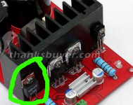
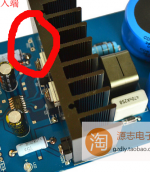
that part is not a gate driver ... it's what I thought was the gate driver at first, but sorry, and congratulations. Your board has excellent overtemperature protection because that's a thermostat. Now remember when you get the board that for that thermostat to work properly, both it and the transistors need to be heat sink greased. All of those components on my boards were little piggies with none, and without it, chances are good your boards will just fry, depending on what you try to do with them and how they are jeweled. What that means is the sad realization I noted at the beginning of the thread. The iraud200 has no dedicated gate driver. It uses the irs2092 to drive the transistors directly. This works fine for low gate charge transistors, but irfb4227 is no such. It requires something like quadruple the gate charge of the little dual transistor packs in the example circuits. Now notice ... no heat sink on the irs2092 chip.... My iraud350s had a heat sink there, and it got hot, and they came with transistors that have only 2/3 the gate charge of irfb4227, which is the only transistor that will get you 2 ohm capability. .. The higher the gate charge : 1: the more current the gate driver has to pass 2: the more current the high side piggy back power supply has to produce. 3: the more likely your irs2092 chip needs a heat sink to help it do what it is not designed for. That means that a board jeweled for one transistor may not be ready to drive one with more gate charge. The result on my iraud350's was mild ... the main heat sink got quite hot, .. I'm guessing because the high side transistor didn't turn all the way on because the piggy back power supply wouldn't supply enough gate current. so I strapped a big heat sink to it and it worked fine until for some reason it became excited and destabilised together with a different amp circuit, which popped the irs2092 chip. I think the reason for the destabilization was some bad connection in the circuitry somewhere which I believe I have repaired, but I'm not promising that ... it could possibly be that the 2092 just got tired of driving a high charge transistor... the evidence however is for the former and not the latter. In any case, it used a heat sink, and yours has none ... at least from the image I can see .. that means that you may be victim to lousy chinese quality control. I strongly advise if when you obtain the boards that you go through a checklist before firing them up because they can be trashed in seconds to minutes if certain errors are present. And first time you fire it up, keep your hand on the heat sink to see how it heats. If the board is working properly, it will only heat up a little during quiescence. BTW ... agree ... don't argue with the chinese, just read this thread carefully and get your board under control so you don't have to cry.
Also, remember that running more than one of these boards off of a single zero volt galvanic unity allows rf to pass from one of the irs2092 chips through the zero volt line to the other .. it can destabilize the chips and even pop them. ... So that means guess what? Fuses are important here ... ok, so next thing is I'm going to try using ferrite beads to impede the rf interference when I finally get my boards properly jeweled. I'm hoping that the great physics God will then allow me to have the boards share a single 0 volt line.
Oh wait ... one of those pics shows a heat sink on the 2092 and the other doesn't. But that is a small heat sink. The ones I am using are about 10 mm x 10 mm x 1.5 inches
Last edited:
- Status
- This old topic is closed. If you want to reopen this topic, contact a moderator using the "Report Post" button.
- Home
- Amplifiers
- Class D
- Iraud200