OK ... next step ... parts came in .. replaced wrong 20k with 10k didn't help .. and after checking the caps over carefully and comparing to new caps in the same range, I discovered that my meter was giving me bad readings because of both zero and span errors, and that the 4 10uf caps are at least 8 uf ... also that they are all ceramic caps and hence nonpolar .. I mistook the dc rating of the cap for an assertion it was polar .. resoldered every joint that looked questionable, didn't help .. so started looking at the circuit. The iraud350 was able to drive the transistors, why not the iraud200? So I looked at the iraud350 ... only one 10 uf cap ... so, how did they do the design without more of them? Look harder ... aaah ... it has 3 47 uf caps .. there are no such on the iraud200 ... Looking them over, comparing to suggested circuit schematics and tracing them around shows that one of these doesn't need to be very big ... it only stabilizes a tiny voltage reference current. A second one is the protection timer, so don't change that. A third one stabilizes Vcc and a fourth stablizes VB... Increasing the capacitance stabilizing Vcc and VB seems to shrink the ripple and allow my meter to read it more reliably. I can now see clearly that Vcc and VBS are both 12 volts solid as recommended and the unit still heats up. What that means is that a: Dead time is at maximum b: gate turn-on power supplies are good, so there is some other reason why it's heating up. .. Transistor gate charge not draining quickly enough? More entertainment to come.
Setting up maximum dead time may cause the body diodes to conduct and make things worse. Distortion also increases. You have to find the optimum set point of dead time - not a simple task.
Nigel, we could use your help about now ... 🙂
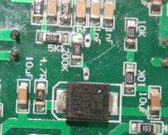
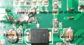
So I have examined the differences between the two boards as well as suggested circuits to look for more clues. At this point, in other words, after stabilizing Vcc and VB, there are two major differences between the iraud200 and the iraud350 that I can see. The first is that the iraud200 has a much larger, but similar looking inductor (with the same nominal value). The second is what I currently believe our problem is. The iraud200 engineers have re-worked the feedback loop. ... DRASTICALLY!!! In the original circuit designs, the feedback loop has a 150 pf delay capacitor that charges through a 1k resistor, so that should add around 300 nanoseconds of delay each on/off cycle. This will considerably slow down the switching frequency. The iraud200 has no such delay capacitor, and in stead of using 51k total loop resistance, they have reached to 205k total loop resistance. What this means is that a: the feedback loop will cause significantly higher switching frequencies and hence higher switching loss. Notice also: they rate it for 50 khz audio range .. .. so this is an indicator that they are aware of the high speed. They are probably using something close to the full 0.8 mhz switching frequency and b:the speed-up could be responsible for some cross-conduction as well as high switching losses both in the transistors, and irs2092 chip and c:there may be some increased sensitivity of the circuit to ambient noise. The sales person asserted that 70 volts was a little high, even though it's rated for 80. That tells me that at say +/- 40 to 60 volts, this thing might be ok because of reduced stress on the components. Personally, I will be driving sub-woofers and would feel happier if the switching frequency were considerably lower. However, it may be good to retain 20 khz response for possible future use, so something similar to the original feedback loop seems to be in order. .. That means I will be ordering some smd components like 1k resistors and 150, 200 and 250 pf delay capacitors. .. a little delay switch would be cool, but not feeling that adventurous. also, 47k, 100k, and 3.3k resistors .. and I think that assortment will wrap up the problem. OK, next adventure on the way .. if/when I get this figured out, people won't have to research it all themselves.
So I have examined the differences between the two boards as well as suggested circuits to look for more clues. At this point, in other words, after stabilizing Vcc and VB, there are two major differences between the iraud200 and the iraud350 that I can see. The first is that the iraud200 has a much larger, but similar looking inductor (with the same nominal value). The second is what I currently believe our problem is. The iraud200 engineers have re-worked the feedback loop. ... DRASTICALLY!!! In the original circuit designs, the feedback loop has a 150 pf delay capacitor that charges through a 1k resistor, so that should add around 300 nanoseconds of delay each on/off cycle. This will considerably slow down the switching frequency. The iraud200 has no such delay capacitor, and in stead of using 51k total loop resistance, they have reached to 205k total loop resistance. What this means is that a: the feedback loop will cause significantly higher switching frequencies and hence higher switching loss. Notice also: they rate it for 50 khz audio range .. .. so this is an indicator that they are aware of the high speed. They are probably using something close to the full 0.8 mhz switching frequency and b:the speed-up could be responsible for some cross-conduction as well as high switching losses both in the transistors, and irs2092 chip and c:there may be some increased sensitivity of the circuit to ambient noise. The sales person asserted that 70 volts was a little high, even though it's rated for 80. That tells me that at say +/- 40 to 60 volts, this thing might be ok because of reduced stress on the components. Personally, I will be driving sub-woofers and would feel happier if the switching frequency were considerably lower. However, it may be good to retain 20 khz response for possible future use, so something similar to the original feedback loop seems to be in order. .. That means I will be ordering some smd components like 1k resistors and 150, 200 and 250 pf delay capacitors. .. a little delay switch would be cool, but not feeling that adventurous. also, 47k, 100k, and 3.3k resistors .. and I think that assortment will wrap up the problem. OK, next adventure on the way .. if/when I get this figured out, people won't have to research it all themselves.
thanks for the idea Voltwide if putting the feedback loop somewhere close to back to spec doesn't help, I'll start looking at dead time.
Success!!!
OK, my next batch of parts arrived today ... basically, I injected a 1k resistor in front of the 200k resistor, and connected the 150pf capacitor from the joint of those to the nearest ground. Turned it on and dreams started to come true. I'm sure the 50khz rating is gone, but no one needed it. I'm sure it's around 20 khz now. The board did heat up quite a bit in the first 5 minutes, but it did not overtemp. (I greased the heat sink to a much larger heat sink) I connected it to a 600 watt driver (a 12 foot bass horn) and started to push. harder, harder, harder, teeth rattling .. still no overtemp ... pretty soon I am smelling voice coil .. whoa whoa whoa back off. So I let it run and run and run at low volumes, and amazingly ... the hot heat sink began to cool down. ... Something changed (for the good amazingly) and I don't know what. That bothers me and excites me at the same time. this board is now working perfectly ... yay ... and btw I feel much safer switching the transistors at only 300 khz or so because that's way less stress on the whole circuit... it promises me longer life of the board. In a day or two, I'll come up with a photograph.
OK, my next batch of parts arrived today ... basically, I injected a 1k resistor in front of the 200k resistor, and connected the 150pf capacitor from the joint of those to the nearest ground. Turned it on and dreams started to come true. I'm sure the 50khz rating is gone, but no one needed it. I'm sure it's around 20 khz now. The board did heat up quite a bit in the first 5 minutes, but it did not overtemp. (I greased the heat sink to a much larger heat sink) I connected it to a 600 watt driver (a 12 foot bass horn) and started to push. harder, harder, harder, teeth rattling .. still no overtemp ... pretty soon I am smelling voice coil .. whoa whoa whoa back off. So I let it run and run and run at low volumes, and amazingly ... the hot heat sink began to cool down. ... Something changed (for the good amazingly) and I don't know what. That bothers me and excites me at the same time. this board is now working perfectly ... yay ... and btw I feel much safer switching the transistors at only 300 khz or so because that's way less stress on the whole circuit... it promises me longer life of the board. In a day or two, I'll come up with a photograph.
Last edited:
more success!!!
I used 5 ferrite beads .. two on one 0 volt line and 3 on the other. I believe this enabled both boards to get along with a single 0 volt line, cause it is working, and historically, 2 of these 2092 boards together on the same 0 volt for me always had trouble. Also note however, THE IRAUD200 HAS AN EXTRA RF FILTER ON THE INPUT That's right ... an extra 1nf capictor and 200 ohm resistor across the input lines. So this thing has already taken measures to shield its self from rf on the input. Once again, these two boards with ferrite beads are functioning together flawlessly. Yay!!!!!!!!!! All except for one single thing.
When I first start up the boards, they warm up and get quite hot, even with a lot of extra heat sink. ... but only for about 5 hours, at which time they cool down and so far it appears that after the initial heat-up, they cool off permanently until the next time you power them up. This is like really weird. I'll be looking for clues to this behavior. I have some foggy ideas, but ... well, not just the main heat sink, but the inductor ... heat up in sync. At one point, I thought there might be some kind of trade-off between dumping energy to the inductor and dumping it to the transistors, but no ..both are either hot or cool. This is suggesting to me that the 2092 chip may have some microcode or something that makes some kind of measurements and adjust its behavior over time, but no memory to remember what it learns. ... Just an idea that could be totally wrong, but these boards have two distinct behaviors ... hot and cool, and they both do it. The difference is huge. Even the heat sink I put on the inductor got so hot that I couldn't touch it more than 1/4 second. Next morning ... cool... and still working. If anyone has any ideas how this happens, please let me know as I would like to know and hopefully even stop it from heating up at the start. So, now I will drop a series of images.
Update
this image shows a large, white 1 uf capacitor. After running the boards for some time, they cooled off ... what I however didn't see because it was covered by the inductor heat sink is that that capacitor went bad or was damaged. It basically partially melted and squirted silver goo out the top. (I'm lucky it didn't short through, that may have destroyed the board) .. Reading the caps while the board is wired in doesn't work ... had to totally disconnect the boards to read them... after doing so, one of them read at 1uf as labelled, the other read at 0.5 uf. The 350 uses 0.47uf here as suggested by the original drawing .. The 1uf idea does suggest they were anticipating more current. (2 ohm) ... I suspect that the caps overheated the same time the other parts got hot .. probably the first time around when the inductor had no heat sink because the cap is right next to it .. in other words ... I wouldn't run this thing without heat sink for the inductor... fact that the inductor got hot proved that the output filters were working hard, which would also effect the caps.
Checking the inductors left me informationless as they read at 0.000 uh by my meter .. it doesn't read that even with shorted leads, so obviously something about the board is messing with the readings. The inductors still attract a magnet, so I know they aren't destroyed even if they have been altered by high temperature. Ferrite/iron powder Inductors can handle up to around 350 fahrenheit I'm guessing these are iron powder. I would expect that for higher frequencies like 800khz. I suspect that the larger caps may have something to do with the boards getting hotter in hot mode than the 350 did.
The boards were working beautifully and not getting hot .. I just dismantled them to start considering reconfiguring and remounting when I noticed the damaged caps. Inspection indicates they are rated for only 100 volts wheras I have other caps here rated for 275 to 400 volts which sounds a lot more convincing, so I opted to solder them out and replace them. .. but I think I definitely don't want to put in anything over 1 uf .. what I have available is 0.47 uf. I think if you are going to order parts to upgrade this board, I would look for high speed nonpolar 0.47 or 1uf caps rated for 200 volts or higher ... A great reason to want higher voltage ratings is that these caps are going to be punished by hf, so strong is good. Removing the cap showed that the board only called for 0.47 uf. It also shows that it calls for 200 volt, which the manufacturer failed to provide. I'm going to guess that since the board was designed for both 4 and 2 ohm operation, 1uf is the right choice for 2 ohm. I think the reason the manufacturer chose a 100v capacitor was probably based on size. my better, smaller caps fit into the same space and are bigger,. actually, anywhere from output to ground including across the resistor on the other side should work. One option would be to ring-terminal a cap onto the input/output terminals. Second thought .. I think I'll do that. Getting new caps into the holes was quite difficult because the top ground plane sucks heat and won't let the solder melt. Finally resorted to use of a very small drill bit and a drill. Then, my strategy of using ring terminals to attach caps to the output/ground terminals double payed off. I left the cap disconnected on one side and was able to verify that during hot mode, both the inductor and the main heat sink on the 0.47uf board ran cooler than the 0.96uf board. The boards agreed because shortly thereafter, the 0.96 uf board overtemped. It had been on for about 2 hours. Because the temperature of hot mode is my chief concern, I think I'm going to consider switching to 0.47uf ... then if I want more filtering, maybe I'll add a third filter pole .. a 10uh or so inductor at the output. It might even work to move to a four pole filter with two inductors and two caps. I'm looking hard to cool the board during hot mode or eliminate hot mode altogether. Anyone with clues is welcome to pipe in. I'm beginning to wonder if the inductors are properly doing their job .. if they drop to low inductance, the caps will start to look like a short to ground. There will be a lot of current flow and heat.. How the board can exhibit two distinct behaviors I still don't understand.

I found I had trouble with output filter capacitors if I forgot to connect a speaker.
The output filter inductor would ring at a high voltage and blow the capacitor.
I fixed the problem by using 250VAC capacitors.
The output filter inductor would ring at a high voltage and blow the capacitor.
I fixed the problem by using 250VAC capacitors.
My red board arrived.
Didn't test it yet, because i'm waiting for the new batteries.
The output filter makes me wonder....
The inductor is a 'double-inductor', its print says '220'.
So this should be two 22µH inductors connected in parallel.
So the right replacement part should be a 10µH inductor with high voltage rating?
This would be much easier with knowledge about the switching frequency, because of a possible swap of the capacitor, too. (my output capacitor looks even worse than mgshightech's)
Are ring-core chokes a good choice on those boards?
@mgshightech:
Thank you for guide to this board/layout.
if it's a silvery cube looking thing with 4 legs ... it's not a double inductor... two of the legs are just for stabilization and connect to nothing. On one of my earlier boards, the manufacturer didn't even bother to solder them. Also, inductors are like resistors ... they add in series and add upside down in parallel. Caps add in parallel and add upside down in series. So, two 10 uh inductors in parallel are 5 uh .. 2 10 uh inductors in series are 20 uh. The good thing about that cube looking inductor is that it readily connects to a heat sink. You need to look and see what transistors the board sports, because that makes a lot of difference in how it will behave. 220 means 22 x 10^0 microhenries. .. so, yes, it's 22 .. there is logic behind all the weird ways of labelling things in this part of the world. Oh yeah ... btw ...the two legs that are the actual inductor are on opposite corners. Comes in one side, wraps around, leaves on the opposite corner.
Also ... my pleasure .. some people just love tech, and making things work ... it's not about stupid green papers, it's about the pleasure of life ;-)
Also ... my pleasure .. some people just love tech, and making things work ... it's not about stupid green papers, it's about the pleasure of life ;-)
Last edited:
the irs2092 is asserted to have max switching speed of 800khz. The 50khz non-modded board will be switching that fast. The feedback loop mod will slow it down to around 200-300khz. The slower switching speed relieves stress on the transistors and inductor, but I don't think it will help the capacitor much. The inductor re-poles its magnetism at the speed of the switching, and hysteresis losses during the switch cause the inductor to heat up ... less switches, less heat. Trust me .. all that heat is not coming from overheated wires inside the inductor from overcurrent. You can't read a resistance across the inductor. It's just a few feet of fat gauge wire.. what raises the inductance so high is the high permeability of the iron powder cubic torus. (toroid core in case of the round doughnut ones) I'm almost sure it's iron powder but the fact that it's so small suggests it may be a low permeability ferrite. .. One article I read said to avoid the doughnut inductors for this application because hf at around 100mhz has no problem penetrating magnet wire insulation via its capacitance (and the transistors do switch that fast.. yes their frequency is 800khz max, but it's a square wave, and the switch speed will be closer to 100mhz) and easily leaks through relatively conductive iron powder. The doughnut inductors may put opposing leads too close to each other, making leakage a problem. I'm going to guess this theory could fail in the case of a ferrite (quite nonconductive) core that is sporting a slot cut in it. Ferrite normally can't handle a lot of power, but if you cut a thin slot in it, its energy storage capacity will rise around 100x because it will store a ton of energy in the space-time vacuum of the slot. (which will then try to radiate some of it) Cut the slot with a tile saw.. make sure it's lubricated and cut slowly or it will chip. I actually made some 22uh inductors for crossovers for my boys speakers that way.. wasn't thinking at the time that the combination of ferrite with slot would likely work better than iron powder for this application. But also ... materials have their own special switch speeds. Most ferrites will have max power around 100 khz. this could change in case of the slot ... iron powder usually handles higher frequencies, but requires a lot more windings because its permeability can be 50x lower.. that means 7x more windings. Because of high permeability however, ferrite saturates easily. That creates a current limitation. Ferrite with slot behaves similar to iron powder. .. only the material is less conductive. You can sort of dial it in by choosing the width of the slot.
Oh btw ... I learned all that scrapping with the solar power charge controller idea, and it occurred to me some time ago that this particular board could probably be modded to operate as a 2-pole charge controller that doubles as a battery voltage balancer, which one could control with an arduino or some such. My head is slowly cracking through the details of that, but it's not top priority just now. However, dual pole solar power with battery balancer would allow for a lot of cool advantages .. for example ... you could feed dc power straight to another board like this to run an amplifier with no power supply, (i.e. lossless power supply for free) or you could invert the power with only half the cost/loss because you could do it with a half bridge in stead of full bridge... This very board could also potentially be modded to operate as a power inverter. There is a lot of genius built into the 2092 chip that boring mosfet drivers don't have. I am seeing this exercise partially as a getting to know the chip thing so that I could play this kind of tricks with it later.
Oh btw ... I learned all that scrapping with the solar power charge controller idea, and it occurred to me some time ago that this particular board could probably be modded to operate as a 2-pole charge controller that doubles as a battery voltage balancer, which one could control with an arduino or some such. My head is slowly cracking through the details of that, but it's not top priority just now. However, dual pole solar power with battery balancer would allow for a lot of cool advantages .. for example ... you could feed dc power straight to another board like this to run an amplifier with no power supply, (i.e. lossless power supply for free) or you could invert the power with only half the cost/loss because you could do it with a half bridge in stead of full bridge... This very board could also potentially be modded to operate as a power inverter. There is a lot of genius built into the 2092 chip that boring mosfet drivers don't have. I am seeing this exercise partially as a getting to know the chip thing so that I could play this kind of tricks with it later.
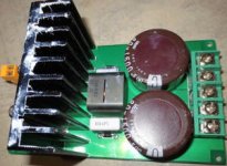
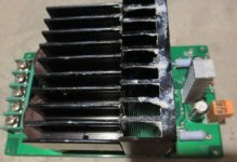
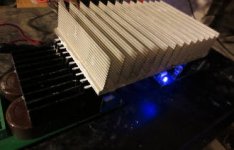
btw ... if you want kickass heat sinks to mount these boards onto for cheap ... heheheheh get this ... go to ebay and look up antminer s1 ... you will see that people are unloading tons of old bitcoin miners for considerably less than the components are worth. You can get $130 of heat sink/fan for around $40. I took one of these antminers and re-configured the location of the heat sinks. I have an old pioneer sx1250 that is powering these boards. It has a transformer good for around 1200 watts. If I grease this heat sink/fan to the top of it, I'm sure I can get more like 1600 or 1700 out of it. Later on I'll show an image of the amplifier with two monster heat sinks mounted to the top side of it. Its power rating will have risen from 160/200 w/ch to 600 w/ch. It will represent multiple pieces of history ... the 1970s hippy music days, the switch to class D amplification, and the cryptocurrency revolution. BTW .. the cryptocurrency revolution is totally legit, so take it seriously. 🙂
Last edited:
mgshightech -
I can't quite tell how the heatsink is thermally connected - is this something that could be tapped for #4 screws for mounting plastic pack FETS, for instance?
Is it usable without fan (or with the fan running slow enough to not make much noise)?
Looks interesting.

I can't quite tell how the heatsink is thermally connected - is this something that could be tapped for #4 screws for mounting plastic pack FETS, for instance?
Is it usable without fan (or with the fan running slow enough to not make much noise)?
Looks interesting.
- Status
- Not open for further replies.
- Home
- Amplifiers
- Class D
- Iraud200