Hi,
I'm putting together a design for a small amplifier that utilises power over Ethernet (PoE). The design specifications are:
- 10w to 30w (as long as >10w power isn't critical)
- 56v asymmetrical power (0v, +56v)
- Stereo in 1 package
- current available only 0.6a (due to PoE specs 802.3at)
- high efficiency (hence class-D)
- Audio quality not that critical (does not need to be audiophile)
- small package with low BoM count
- $5 - $8 per chip in medium volume
- I2S input ideally but will take analogue instead
Spending time searching the usual suspects (TI, NXP etc.) seems its difficult to find higher voltage class D chips as they are typically meant for high power amps and also are higher cost or complex (eg. the TI TAS56xx range) with fairly low efficiency at lower power for class D. The simpler chips more suited to my application are all lower voltage, typically 24 - 36v. I'm also obviously constrained with current although a decent electro on the power supply with provide much higher 'peak music power'.
My questions:
1) Anyone know of any chip that may be suitable that I may have missed?
2) There are a couple of chips that are in this voltage range but require symmetrical power (+- 28v) however I'm not sure if they can be tricked into running on symmetrical power 0v, +56v) without running in bridge mode which turns them into mono amps. Any tips on how to do this (eg. TDA8922 is a candidate)
3) the Ti TAS56xx chips would be somewhat suitable (price and efficiency not great) if they could use a slightly higher voltage. 56v is within the absolute maximum voltage specification but obviously I'm nervous running them a little bit outside their recommended maximum voltage.
I'm considering using a buck regulator to drop the voltage however this adds complexity, size and lowers efficiency.
Any ideas greatly appreciated.
Looks to be a dead ringer for an output transformer. Then you can trick the NXP chip into running bridged from asymmetrical power (but of course you'll need 2). Since your power requirement is very low your trafo only need be a small one - I'd suggest a 5VA.
Interesting. I think the TDA8922 can run bridged without a transformer if a virtual earth is used at the input. But as this is a mono configuration and as I have limited room for a second chip + components this approach isn't suitable. I wonder if a transformer can work on a single ended output - I don't think so.
Yep, a transformer will work on an SE output. Trafos need coupling caps anyway no matter the config since even a small DC offset will tend to saturate the core.
Nice to see that this discussion goes on without the smallest thought being wasted on the actual power supply capabilities or absolutely unrealistic specs 🙄
A 56V supply, with peak capability of 0.6A and driving stereo speakers to boot, can have a useful signal swing of, say, 50V peak to peak or some 50/2=25 peak volts or 25*.707=17.7V RMS .
Since 0.6A peak are available for stereo, half that is available for a single channel, or 0.3A .
So load impedance will be 25V/0.3 A=83.3 ohms ... good luck finding such speaker folks 🙄
Power at clipping will be 17.7^2/83.3=3.7W RMS
Sorry for the reality shock .
Precisely the reason for the trafo. A 2:1 step down ratio gives impedance transformation of 4X making 8R look like 32R. The peak power can be handled easily enough by the local cap as even the most heavily compressed music has >10dB peak/average ratio. Of course the amp needs to be classD not to waste most of the power in the heatsink.
I'd use a LM5576 buck converter to drop +56V down to 18-24V, and use a TPA3123 operating from the lower voltage to drive your speakers. Use a cheap 1-bit DAC to feed the TPA3123.
Cheap parts, won't take up much PCB, can be done 100% surface mount... I don't think you'll find a cheaper solution. Audio output transformers aren't small or cheap.
Cheap parts, won't take up much PCB, can be done 100% surface mount... I don't think you'll find a cheaper solution. Audio output transformers aren't small or cheap.
OP doesn't require high quality, mains EI trafo rewound for the application will be cheap in parts ($1 or so here for the trafo, extra for the wire) but costly in time. Bigger and heavier than an SMT PCB for sure.
Helpful discussion, thanks.
I'm not so worried about the lack of current - a large electrolytic will store enough energy to feed the music transients. This solution is for background music and voice (in wall system) so isn't going to be used for immersive heavy metal at high volumes. A 1000uF cap at 56v can (ideally) store 1.5 Joules of energy, which equates to around 30w of extra power available for a 50mS transient peak.
However even with the extra current from the cap, the load impedance will still be somewhat high (assume 1A per channel during peaks still is 25 ohms) but definitely workable 17.7v^2 / 25 = 12w.
A transformer is interesting as it could replace the class D output inductor, I assume for single ended output with an asymmetrical power supply you would wire the primary between the amp output and the 0v line.
I had thought of the switcher previously, and it will provide more current when dropping the voltage, but it has efficiency losses and extra cost/size (I'm size constrained as well).
So basically my options are if using a chip like the TDA8922 (which needs a symmetrical supply) and trying to use it with a asymmetrical supply and single ended output, it can work with a virtual earth on the input and a transformer on the output (I assume you can't connect the speaker when running SE direct from output to 0v). Alternatively use a switcher to drop the voltage and use more standard parts - although using the TDA8922 in bridge mode will be more efficient (& no transformer) but 2 amps are required for stereo, a similar parts count to using a switcher.
Am I missing any other option?
A transformer is interesting as it could replace the class D output inductor, I assume for single ended output with an asymmetrical power supply you would wire the primary between the amp output and the 0v line.
Via a DC-blocking cap. I'd suggest 1000uF/35V - it 'sees' half the total supply.
<afterthought> Replacing the OP inductor might work, though I'd be concerned about the trafo's self-capacitance. At the switching frequency (typically a couple of hundred kHz) trafos tend to look like capacitors.
Last edited:
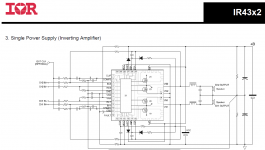
After a couple of hours 'net searching I came across a chip that looks almost ideal, IR4322 from International Rectifier which can cater for 60v single supply, stereo, minimal components. However it seems this chip isn't very popular and even digikey/mouser don't stock it!
I'm not entirely clear about the implementation differences between single and dual supplies are for Class-D. What is interesting is that the schematic for the IR4322 for single supply (see attached) has a resistor divider on the output as the gnd return for the speaker, yet this doesn't make sense as the resistor would not be able to carry the output current.
Looking into the audio transformer it seems would be quite bulky at the frequencies we are talking about (not to mention possible EMI problems as abraxalito points out). I'm not understanding why the transformer is needed if a blocking cap is used on the output, as the transformer primary just looks like a load connected to ground from the amp output perspective (mosfet half bridge).
Attachments
The trafo is needed so that your rather weak 56V PSU does not collapse under the strain of driving a raw 8R (or heaven forbid, 4R) drive unit. Put simply, there's insufficient current available, even with the local storage cap.
A trafo primary looks like a large inductor (typically 1H or more) so does not load the amp much except at the very lowest frequencies (below audio).
A trafo primary looks like a large inductor (typically 1H or more) so does not load the amp much except at the very lowest frequencies (below audio).
- Status
- Not open for further replies.
- Home
- Amplifiers
- Class D
- Help selecting a class D chip - stereo with 60v power