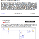
...bypass caps are about an inch further from the mosfets. What I can do for now is to put another rail to rail SMD cap in the exposed tracks.
...too bad, I was pretty happy when I thought that I would have discovered them.Also there are no ceramic caps on the mosfet pins 😱 🙁, they are bleeder for gate drive..
Well, let's see how your power stage works with the IRS2092.
If necessary - somehow you will find some space to manually solder the ceramics close to the Fets like C13, C14, C17, C18, C19, C21, C27, C28 in my schematic / PCB.
Somehow sad that you skipped them here.In all of my other layouts, bypass caps are sitting next to the mosfets' pins.
Yes, it means disconneting the speaker while the amp delivers high power, i.e. opening a speaker protection relay.I don't get what load dump means. Is this connecting/disconnecting a speaker? Can you explain this further?
R38 and C23 are intended to provide a mostly resistive load for the amp in the frequency range 200kHz...1MHz.R38 and C23 are intended to be put on speaker terminals on the chassis
With speaker wires between amp and RC you will add multiple uH series inductance.
The RC becomes a LRC. Depending on wire type and length you will get something. It can improve or weaken the function of the RC or just make it meaningless.
D
Deleted member 148505
...too bad, I was pretty happy when I thought that I would have discovered them.
Well, let's see how your power stage works with the IRS2092.
If necessary - somehow you will find some space to manually solder the ceramics close to the Fets like C13, C14, C17, C18, C19, C21, C27, C28 in my schematic / PCB.
Somehow sad that you skipped them here.
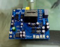
I got difficulty in this kind of layout since the mosfets are on the side of the PCB, I wasn't able to provide ground plane on the mosfet area.
Goal of the layout is to have an easier heatsink mounting, with mosfets under the PCB, so I sacrificed some guidelines, so in the process I will find how forgiving the IRS2092 based amp will be, and how the performance will fair in comparison on the optimized original layout.
The board is only 3.4" x 3.9", less than 10cm x 10cm so that manufacturing will be very cheap.

Yup usually inside the chassis, around a foot of wire is added and sometimes passes through a relay. Maybe i'll use 5W vertical resistor for the R38 on the PCB to save space. (although it's expensive)R38 and C23 are intended to provide a mostly resistive load for the amp in the frequency range 200kHz...1MHz.
With speaker wires between amp and RC you will add multiple uH series inductance.
The RC becomes a LRC. Depending on wire type and length you will get something. It can improve or weaken the function of the RC or just make it meaningless.

One foot of wire is fine. Anything up to 2-3ft should be trouble free....around a foot of wire is added and sometimes passes through a relay...
Edit: The relay inbetween obviously is less fortunate, because then the RC gets disconnected from the amp in the moment the relay opens.
Last edited:
D
Deleted member 148505
Yes, it means disconneting the speaker while the amp delivers high power, i.e. opening a speaker protection relay.
IRS2092 based amps are quite rugged on load dump, I have no problems encountered on pre-filter feedback types. Zero failure
Nice to hear that. IRS2092 based amps also survives resonating unloaded output filter, even without zobel, they only dissipate around 10W to 15W, the antiparallel diodes on the output are shunting the energy back to the rails. To save energy, there should be a mechanism in which when there is no load or the relay is opened, the SD pin should be pulled down to stop the self oscillation of the amp.One foot of wire is fine. Anything up to 2-3ft should be trouble free.
Edit: The relay inbetween obviously is less fortunate, because then the RC gets disconnected from the amp in the moment the relay opens.
IMHO you are describing exactly what happens and possible emergency countermeasures when an amp is not properly stable. If the loop is designed really nice with correct parametrization then all the pills are not needed.... they only dissipate around 10W to 15W, the antiparallel diodes on the output are shunting the energy back to the rails. To save energy, there should be a mechanism in which when there is no load or the relay is opened, the SD pin should be pulled down to stop the self oscillation of the amp.
Nevertheless sometimes it is fortunate to have the pills 😀
D
Deleted member 148505
Yes, IRS2092 IRAUDAMP reference designs do exhibit instability on open loads (on certain scenarios). Specially when 2 modules are sharing the same supply and is poorly wired on the chassis (might have some ground loops): If there is load connected, they are stable, but when there is no load + combined with certain signal source or poorly wired preamp , instability happens.
IRAUDAMP9 has a different approach, they removed zobel and the antiparallel diodes which allows the output peak to exceed -B voltage on filter resonance, which is detected by HOPS circuit. I haven't tried it though.
IRAUDAMP9 has a different approach, they removed zobel and the antiparallel diodes which allows the output peak to exceed -B voltage on filter resonance, which is detected by HOPS circuit. I haven't tried it though.
Attachments
D
Deleted member 148505

Yes, I'm also like that. It's like bewitched. One gets compulsive... 😡... I always forget some parts when ordering... 😱
Nice Board 🙂
 ..oh really? Never happened to me..
D
Deleted member 148505

Nicely build.
...usually in a new build there are some errors, however I trust you will get it going. And of course feel free to ask, in case things go mad.I hope it will work.. lol
D
Deleted member 148505
Nicely build.
...usually in a new build there are some errors, however I trust you will get it going. And of course feel free to ask, in case things go mad.
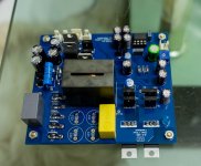
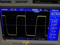
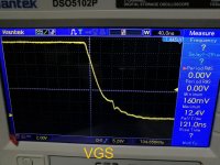
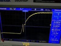
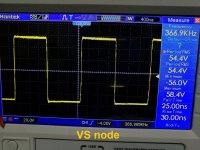
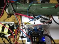
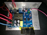
It is working at first power up, I just checked VSS/VAA/VCC if the voltages are ok before powering up. Sounds good, no distortion, however, I can't adjust the oscillating frequency, it is stucked at 340khz even if i'm already using 1k trim pot. Not changing a bit even trimpot is adjusted. When I put zobel, it increased to 366.9khz.
IRS2092 deadtime preset is DT3, and I'm using IPP320N20N3 output mosfets. Output inductor 1D31A-150MC.
External power supplies are batteries with MT3608 boost converter to provide +/-15V ref to ground and +15V ref to -V.
I'll be changing gate resistors to make rise and fall time slower. Also I'll review the schematic, might have some errors.
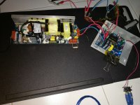
Attached pics.
Attachments
It is working at first power up, I just checked VSS/VAA/VCC if the voltages are ok before powering up. Sounds good, no distortion, however, I can't adjust the oscillating frequency, it is stucked at 340khz even if i'm already using 1k trim pot. Not changing a bit even trimpot is adjusted. When I put zobel, it increased to 366.9khz.
IRS2092 deadtime preset is DT3, and I'm using IPP320N20N3 output mosfets. Output inductor 1D31A-150MC.
External power supplies are batteries with MT3608 boost converter to provide +/-15V ref to ground and +15V ref to -V.
I'll be changing gate resistors to make rise and fall time slower. Also I'll review the schematic, might have some errors.
Attached pics.
😛 its been a while since I've been here. whats going on here I see a remix and it looks good.
Hi JLesterP
Nice build, and nice results so far. Congrats
What is the SMPS you are using?
BR Baldin
Nice build, and nice results so far. Congrats
What is the SMPS you are using?
BR Baldin
D
Deleted member 148505
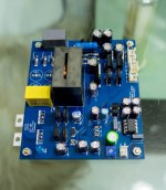
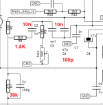
I forgot to mention that I'm using the 80V BOM, I changed R8 to 1.8K ohms, now the oscillating frequency is adjustable.
Highest operating frequency with 1k trimpot + 150R is 360khz, then 430khz if there's zobel, and 445khz when there's 8R resistive load attached.
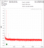
I'm getting high-ish THD measurement even when the preamp is bypassed. THD 1khz is 0.003% to 0.02% 1W to 100W at 8R. Gate drive is not optimized yet, i'll re-measure THD after I tweaked it.
Highest operating frequency with 1k trimpot + 150R is 360khz, then 430khz if there's zobel, and 445khz when there's 8R resistive load attached.
I'm getting high-ish THD measurement even when the preamp is bypassed. THD 1khz is 0.003% to 0.02% 1W to 100W at 8R. Gate drive is not optimized yet, i'll re-measure THD after I tweaked it.
Attachments
D
Deleted member 148505
😛 its been a while since I've been here. whats going on here I see a remix and it looks good.
Hi JLesterP
Nice build, and nice results so far. Congrats
What is the SMPS you are using?
BR Baldin
Thank you!
I'm using Abletec +/-53V.
I forgot to mention that I'm using the 80V BOM, I changed R8 to 1.8K ohms, now the oscillating frequency is adjustable.
Yup, your red values are Ok for the 80V version.
In an older set up of my 80V experiments I also used 1k8 for R8.
Regarding distortion, please note that also my 75V and 80V versions
have more distortion that the 40V version.
0.003% would be close to my 75V & 80V results (0.002%) at 1kHz & 1W/8 Ohms when powered with voltages around 75V..83V (ref. attached measurement).
But I am scratching my head what means 0.003% to 0.02%. Shouldn't it be just one value for a certain condition?
Under which circumstances do you get the 0.02%?
Nevertheless anything below 0.1% can be regarded as normal when stepping to a new power stage and layout without detail fine tuning afterwards.
Your results after first turning on are looking like a very nice starting point. Congratulation!
Attachments
IRS2092 deadtime preset is DT3, and I'm using IPP320N20N3 output mosfets.
... I see. Some years ago I experimented with them while designing my 2kW amp and found that they make it difficult to achieve outstanding THD.
In general the nonlinearity of Coss is a relevant parameter for THD optimization. IPP320N20N3 is pretty extreme in this parameter.
The massive increase of Coss towards Vds below 30...40V is demanding for comparably long dead times in order to have low switching losses during idle.
I did not find a satisfying adjustment of dead time, idle losses and THD, at that time and decided to stay with the IRFP4668 monsters 🙂.
Theoretically I would expect a strong influence of the supply voltage on the THD iny our case. Did you check it at different voltages?
Towards high supply rails I would expect better results.
Note:
Infineon did not make everything wrong with the IPP320N20N3. In
many applications this characteristic is fine. Just for low THD class D designs it is not my favorite.
D
Deleted member 148505
Yup, your red values are Ok for the 80V version.
In an older set up of my 80V experiments I also used 1k8 for R8.
Regarding distortion, please note that also my 75V and 80V versions
have more distortion that the 40V version.
0.003% would be close to my 75V & 80V results (0.002%) at 1kHz & 1W/8 Ohms when powered with voltages around 75V..83V (ref. attached measurement).
But I am scratching my head what means 0.003% to 0.02%. Shouldn't it be just one value for a certain condition?
Under which circumstances do you get the 0.02%?
Nevertheless anything below 0.1% can be regarded as normal when stepping to a new power stage and layout without detail fine tuning afterwards.
Your results after first turning on are looking like a very nice starting point. Congratulation!
Hi Choco, thank you, I used +/-53V DC for my THD measurements, so I expect that the results should be lower than with +/-80V DC supply. I haven't tried to measure the THD on higher rail voltage.
0.003% @1W 8R and 0.2%(typo earlier) @100W but I didn't make screenshots since the results are not that good.
Filtered output carrier only has very small blip (got lucky), also VS node square wave has some ringing on turn off, it might be gone after I adjust the gate resistors.
My reference is my other class-d prefilter IRS2092 (JLE-1500D) which has the same buffer stage, but uses IRFB4227 and DT4 IRS2092 deadtime preset. It got 0.0016% @ 1W 8ohm, and 0.016% @ 100W 8ohms. Using the same power supply. +/-53V DC. But it has a better layout, so no surprise that it got better result.
As for the sound, this one (liteamp) has totally different character than default prefilter IRAUDAMP7, it is more laid back, the voice is not forward sounding unlike the prefilter type, but I think it has more soundstage because of it.
... I see. Some years ago I experimented with them while designing my 2kW amp and found that they make it difficult to achieve outstanding THD.
In general the nonlinearity of Coss is a relevant parameter for THD optimization. IPP320N20N3 is pretty extreme in this parameter.
The massive increase of Coss towards Vds below 30...40V is demanding for comparably long dead times in order to have low switching losses during idle.
I did not find a satisfying adjustment of dead time, idle losses and THD, at that time and decided to stay with the IRFP4668 monsters 🙂.
Theoretically I would expect a strong influence of the supply voltage on the THD iny our case. Did you check it at different voltages?
Towards high supply rails I would expect better results.
Note:
Infineon did not make everything wrong with the IPP320N20N3. In
many applications this characteristic is fine. Just for low THD class D designs it is not my favorite.
Ok i'll replace the output mosfets with IRFB4227 for more even comparison with my other class-d, also will be changing supply for my next measurements, I think the boost converter that I used for +/-15V supplies added interference on my measurements..
Attachments
Last edited by a moderator:
It got 0.0016% @ 1W 8ohm, and 0.016% @ 100W 8ohms. Using the same power supply. +/-53V DC.
I see. Hm, 0.016% @ 100W into 8 Ohms with a +/-53V supply is extremely good. 100W into 8 Ohms means 28.3Vrms, means 40Vp. And at the same time the 53V might sag a little bit. So this is already a pretty high level of PWM modulation, where also the modulator distortion is likely to grow substantially.
I do not think that you will get the 80V version to 0.016% @ 100W into 8 Ohms while running with a +/-53V supply. However I must admit that I had spend my THD optimization efforts to the 40V version, so I cannot tell what really can be achieved with the 80V versions. I just added them in order to show further options. So I am curious about your tweaking. In any case I am convinced that good old Nelson is right with his 'first Watt' approach. The first Watt is what makes the sound under normal listening conditions. Optimizing amp distortion at higher levels is most likely irrelevant as long as the speakers come along with multiple full % at higher levels. On the other hand - for curious nerds it is always fun to investigate.. 😉
About the difference in sound:
...good question what is more correct...
Most likely in audio there is no other way than people listen to it and then decide what they like more. Personally I found my love with my 2kW design. Despite it measures by far less good than the nCore, I like it more. 😱
- Home
- Amplifiers
- Class D
- SystemD LiteAmp