yep it's the sure board, but lenta thinks about T2 for multichannel amp.
You can remove the pots. It's easy to replace the caps on T2, I don't like to leave input caps off board, but if you feel like it,why not.
Thank you for replay!
If pot is ofboard then it must be conected to all T2 with wires, so I thought it would be better to use caps with its long enough leads.
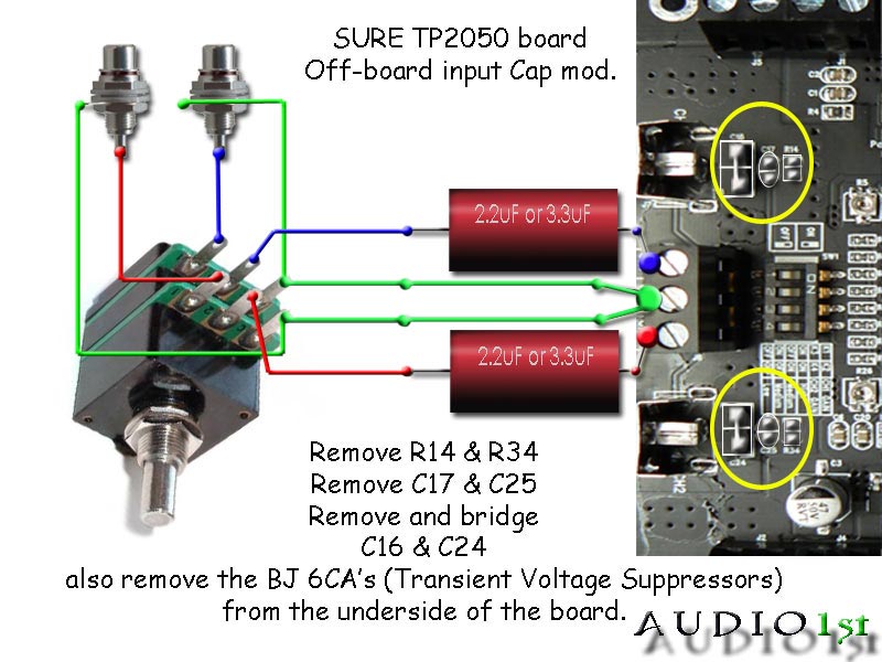
But caps are there not only for DC blocking, maybe thats why in these sure mods you need to remove some other caps?Is it that easy on T2?

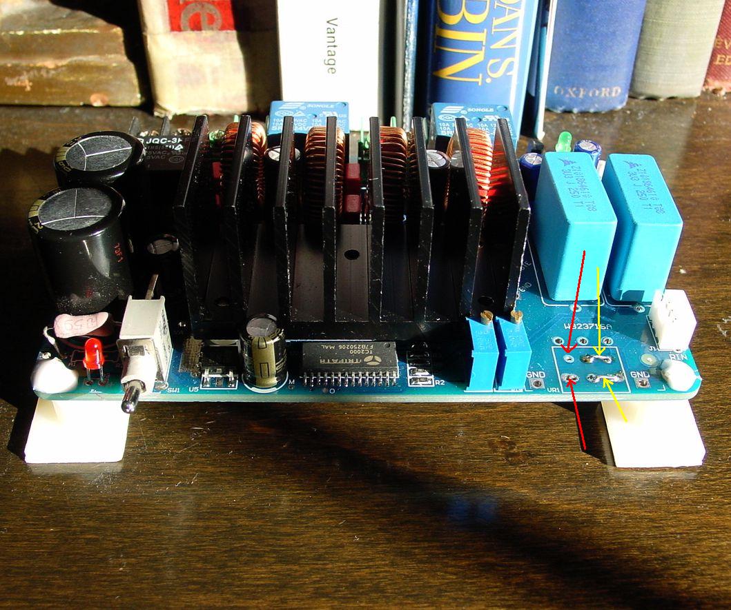
Hope this helps, this is a picture of a T1, T2 similar. I removed the pot, notice I had to jumper two of the pot contacts (yellow arrows).
Also, red arrows show where external pot feeds in. I also replaced the input caps, but decided to leave these on board since the new ones fit.
Also, red arrows show where external pot feeds in. I also replaced the input caps, but decided to leave these on board since the new ones fit.
Attachments

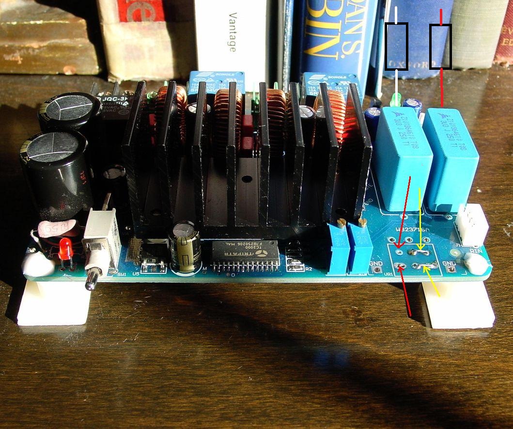
In the above, the jumper are needed because the molex plug is used for input signal.
If you don't have molex connectors or don't want to use this plug, you can solder the input signal cable directly to the board. No jumper needed.

Thanks Alkasar, I knew there was something I was forgetting late. Never mind my red arrows, if you jumper like I did, you must use the Molex connector for your input.
Update on the T1, it has met and surpassed expectations. I love the way the bass goes down low, what a nice welcome performance from a T-class amp. The mid continues to do its magic.
I basically follow something very similar to the advanced linear solid state power supply described by TNT audio: Solid State Power Amplifier Supply Part 1
You'll see the schematic there on Part 3. Now keep in mind this power supply is for + 0 - , since this amp only uses + 0, then only use half the schematic on the transformer secondary side. Meaning, no negative voltage needed.
Additionally, I do some AC line filtering that is common to PC power supplies. I use an X class capacitor across the mains AC and Y class capacitors on each main line to ground. Also use a bleeder resistor across the mains. I do not use chokes in order to no affect transients surge and do not use power strip with surge suppression. I got that advise from the head engineer at Grapevine Audio, he really knows this stuff quite well.
You can also see it better in this picture, I feed the amp right off the soldering block.
Another lurker emerges into the Hfimediy TK2050 arena.
I too, am interested in this PS. I can develop a schematic from the photo, but would you be so kind as to list component types/values and transformer spec.s?
I just received a T1+Meanwell, and would like to try a linear PS as well.
In the above, the jumper are needed because the molex plug is used for input signal.
If you don't have molex connectors or don't want to use this plug, you can solder the input signal cable directly to the board. No jumper needed.
FWIW, on my T2 I wanted to keep the volume pot, but I believe in general that the fewer connectors the better. Some folks believe that each connector joint has variable resistance and capacitance that degrades the signal - I'm not sure about that, but if I can eliminate a connector, why not? So I desoldered the Molex input connector and soldered the input wires directly to the board.
(I also have the speaker wires with new-stripped copper at both ends screwed directly down. If the boards could handle it, I would solder them directly, too, at the amp end. And at the speaker end, no banana plugs or such, just direct copper to the terminals. You have to re-strip and re-tighten every now and then, but it sure sounds good to me. But I digress...)
Thanks everybody!
Very nice pictures!
If I connect input like in picture it will work? Or both sides off cap must contact with the board? I have no boards yet, but it is important to know before.
I am very interested in high pass filter which can be done using input caps.
For example if I want to roll off bass from my 4 ohm full range driver at 150 hz i would need to use 250 uf cap usualy, but using amps input caps like high-pass filter i would need to use 0,047 cap instead.
With second amp i will connect tweeter only, and using input cap value off 0,001 I would cross it at desired frequency 8000 hz.
It would be cheaper and probably better sounding too.
What are your thoughts, and is there some drawbacks?Phase shifts?
There are discusion about high-pass using input caps
http://www.diyaudio.com/forums/class-d/143669-sure-electronics-new-tripath-board-tc2000-tp2050-87.html
http://www.diyaudio.com/forums/class-d/143669-sure-electronics-new-tripath-board-tc2000-tp2050-87.html
Here's my T3 build in black tinted acrylic box. Box custom made for minimum cabling
An externally hosted image should be here but it was not working when we last tested it.
An externally hosted image should be here but it was not working when we last tested it.
Here's my T3 build in black tinted acrylic box. Box custom made for minimum cabling
Acrylic remember me something in my signature.
Cooling ? acrylic doesn't like heat : some ventilation anywhere ?
Thanks guys
I wouldn't use acrylic for Class A, AB and tubes on account of heat, but Class D is another matter
Yes the box has ventilation. See the holes at the back panel near the lid, and there are many holes drilled under the smps, heatsinks and psu board for airflow. We have those smps fans should the party get too hot in there. The temp inside measures 8deg C higher than room when the amp is playing music. This amp hardly exceeds 22W power consumption playing at various volume levels, checked with a power meter!
Those 20,000uf/ch caps are the new hifimediy stock caps! No problem at all with the smps and I think more power reservoir is usually better. With smps and the big caps this psu section should have the testosterone for anything. Music keeps on going on for 10 secs after amp is switched off.
I wouldn't use acrylic for Class A, AB and tubes on account of heat, but Class D is another matter
Yes the box has ventilation. See the holes at the back panel near the lid, and there are many holes drilled under the smps, heatsinks and psu board for airflow. We have those smps fans should the party get too hot in there. The temp inside measures 8deg C higher than room when the amp is playing music. This amp hardly exceeds 22W power consumption playing at various volume levels, checked with a power meter!
Those 20,000uf/ch caps are the new hifimediy stock caps!
No problem at all with the smps and I think more power reservoir is usually better. With smps and the big caps this psu section should have the testosterone for anything. Music keeps on going on for 10 secs after amp is switched off.Bernie
Your acrylic builds look great. Really nice job.
Still waiting on my power supplies to arrive. Chinese New Year is a very long holiday!
Uriah
There's the 12 days of Christmas, and then there's the 15 days of Chinese New Year
Yup the whole of China is on virtual shutdown at this time.Thanks for those caps pal, they've been put to good use :
VERY nice, Bernie7!
Tired of waiting for T4 and was thinking of doing the T3 thing instead, but now those are out of stock, too. Oh well.
Would like to add a Broskie tube buffer, too, even though it probably doesn't need it, since I am curious about how that would sound.
Tired of waiting for T4 and was thinking of doing the T3 thing instead, but now those are out of stock, too. Oh well.
Would like to add a Broskie tube buffer, too, even though it probably doesn't need it, since I am curious about how that would sound.
- Status
- This old topic is closed. If you want to reopen this topic, contact a moderator using the "Report Post" button.
- Home
- Amplifiers
- Class D
- New TK2050 board