1000 times too big
1000 times larger than we need but fun to look at any way. Can't believe Parts Express actually stocks those.
1000 times larger than we need but fun to look at any way. Can't believe Parts Express actually stocks those.
Gauge 22 wire = dia 0.64516 mm
Refer MIL-STD-975.
Wire Bundle Ampacity (per wire) = 2.22A
Also Maximum frequency for 100% skin depth for solid conductor copper is: 42 kHz
For TP2050 working freq is xxx KHz to over 1 MHz.
For max output you need about 5A RMS, even for DC the about wire dia. is not enough, also it's not all area for transfer that current at the working freq, skin effort have to also consider.
It seen strange that, according to the specification, Tripath even have difficulty to deliver the power just out of the chips.
My AWG table says power handling for 22ga is .92 amps. But it depends on how you're using it and Mil Spec clearly defines power handling differently than AWG. It's all about voltage drop and heat generated. AWG says meltdown for 22ga is 7 amps.
While the Tripaths do work to over 1 meghz, the coils are filters to roll off the frequency at around 80 khz.
90 watts at 30 volts is 3 amps, no matter what your impedance is. W=V*A. And the TK2050 has pretty high distortion at 90 watts, so I don't think most of us will be pushing it that hard. 60 watts is more reasonable and that's 2 amps at 30 volts. A 3 amp continuous power rating on the coils is plenty.
-dr_vega
These 10uH toroid coils look good. Rated for 6.7A. $2.08 each for 10
http://www.mouser.com/Search/ProductDetail.aspx?R=2301-V-RCvirtualkey54200000virtualkey542-2301-V-RC
Very large at 30mm though.
According to Tripath, the core material is critical. Those don't say what they are. Here's the quote from Tripath's datasheet for the TA2022 (which has the same requirements as the TK2050):
"Output inductor selection is a critical design step. The core material and geometry of the output filter inductor affects the TA2022 distortion levels, efficiency, over-current protection, power dissipation and EMI output. The inductor should have low loss at 700kHz with 80Vpp. It should be reiterated that regardless of the systems maximum operating current, a 10A rating is required to ensure that peak current conditions will not cause the inductor to saturate. During a short circuit event the inductor current increases very quickly in a saturated core (see figure 6), compromising the current protection scheme. A 10A rating is sufficient to ensure that current increases through the inductor are linear, and provides a safety margin for the TA2022. There are two types of inductors available in the 10A range that offers some EMI containment: they are the toroidal type and the bobbin (shielded) type inductor.
In bobbin construction, a ferrite shield is placed around the core of a bobbin inductor to help contain radiated emissions. This shield can reduce the amount of energy the inductor can store in the core by reducing the air gap, which can lower the peak current capability of the inductor. Typically, a 7-10A shielded bobbin inductor will not have the peak current capability necessary to ensure that the core will not saturate during short circuit events; this is why they are not recommended for use with the TA2022. Also it should be noted that shielded bobbin construction is not as effective as toroidal construction for EMI containment.
Tripath recommends that the customer use a toroidal inductor with a Carbonyl-E core for all applications of the TA2022. This core has a high peak current capability due to its low-μ Carbonyl-E metal powder. A distributed air gap increases its’ energy storage capability, which allows for a small footprint and high current capability. Carbonyl-E toroidal iron powder cores have low loss and good linearity. The toroidal shape is ideal for EMI containment. Also, EMI can be further contained by sizing the toroid to accept a full layer of windings. This aids in shielding the electric field. Tripath recommends:
- Micrometals (www.micrometals.com) Type-2 (Carbonyl-E) toroidal iron powder cores. The specific core Tripath initially verified and used on the EB-TA2022 was a T94-2 (23.9mm outer diameter) wound to 11uH with 19AWG wire. Since then Tripath has determined that much smaller Carbonyl-E toroids will not saturate during high current events. Tripath has
also used T68-2 (17.5mm outer diameter) and the T60-2B/60(15.2mm outer diameter) cores wound to 11uH with 22AWG with good success. If a smaller core is required, core outer diameters as small as 15.2mm (T60-2) work well, but core temperature effects should be tested. The T60-2 core did not saturate during short circuit testing, but maximum core temperatures must be considered and multiple layer winding must be used to achieve 11uH. Multiple winding can increase winding capacitance, which may cause ringing and increased radiated emissions. Bank winding techniques can minimize this effect. It should be noted that at core temperatures above 130C the single build wire used by most inductor manufacturers should be replaced with a heavy build wire. Micrometals does not provide winding services, but many companies purchase directly from them and provide completely finished inductors. Pulse Engineering has assigned a part number for the T68-2 wound with 44 turns of 22 AWG single build wire. The part number is PA0291.
- Amidon Inc./American Cores type-06 (Carbonyl-E) toroidal iron powder cores. Tripath has used T690-06 (17.5mm outer diameter) cores wound to 11uH with good success. Amidon carries type-06 cores in the 23.9mm to 15.2mm outer diameter range. They have assigned a part number for the T690-06 wound with 44 turns of 22 AWG single build wire. This part is approved by Tripath and is 690064422."
-dr_vega
1000 times larger than we need but fun to look at any way. Can't believe Parts Express actually stocks those.
Hi sendler, I didn't notice that it was you. I want to thank you for your website. I gleaned lots of useful info from you on upgrading the Behringer 4096 products and about audio in general.
I think people building high end speaker crossovers buy those coils from Parts Express. I bet they sell quite a few.
-dr_vega
Nice filter
Nice work. That looks like the filter to try. I like the idea of smaller coils which can be air core, and bigger caps which are still only 1uf all around. No need to miniaturize in my application.
Thank you, ElFishi, for the nice article. I don't fully understand it but I am getting a better idea of output filters.
If I understand correctly, what's known as "common mode filter with damping resistors" in the article seems to be the design to go for if I am willing to spend a little more on the multiple film capacitors required by it.
Can you guys check if I have understood correctly and have made correct calculations? I tried to come up with the values to be used for the inductors, capacitors and registers for this design by following the article.

I am assuming cut-off frequency of 80KHz as written in the Tripath manual and Speaker Load resistance of 4Ohm (for my speakers)
The optimum value for the filter inductor is L = RL/2pi fc, according to the article so this gives me the L value of 7.968127 uH , or about, 8uH
But since the total inductance is divided between two inductors,
L1 = L2 = ½L = RL/(4 pi fc) = about 4uH
And the capacitors are
C1 = C2 = C3 = C4 = 2/((2pi fc)2 • L) = 1/((2 pi fc)2 • L1) = 0.98946uF or about 1uF
and
R1 = R2 = 1/(√2 • 2pi fc C1) = 1.4067442 = about 1.4 Ohm
Am I understanding it correctly? Have I made the calculations correctly?
Nice work. That looks like the filter to try. I like the idea of smaller coils which can be air core, and bigger caps which are still only 1uf all around. No need to miniaturize in my application.
I see, thanks for your kindly explanation, I think the power means the power output to the speaker (4 ohms) not the power drain from power source, right?My AWG table says power handling for 22ga is .92 amps. But it depends on how you're using it and Mil Spec clearly defines power handling differently than AWG. It's all about voltage drop and heat generated. AWG says meltdown for 22ga is 7 amps.
While the Tripaths do work to over 1 meghz, the coils are filters to roll off the frequency at around 80 khz.
90 watts at 30 volts is 3 amps, no matter what your impedance is. W=V*A. And the TK2050 has pretty high distortion at 90 watts, so I don't think most of us will be pushing it that hard. 60 watts is more reasonable and that's 2 amps at 30 volts. A 3 amp continuous power rating on the coils is plenty.
-dr_vega
therefore the equation: P = I * I * R should still applicatable.
When discuss with you, I seen like a primary class student and can learn great deal from you.
My AWG wire info are gather from here:
http://www.powerstream.com/Wire_Size.htm
http://circuitcalculator.com/wordpress/2007/09/20/wire-parameter-calculator/
Last edited:
Nice work. That looks like the filter to try. I like the idea of smaller coils which can be air core, and bigger caps which are still only 1uf all around. No need to miniaturize in my application.
I was very eager to try this design after having read the article brought to my attention by Elfish, but I am having trouble with two issues:
1. Obtaining appropriate inductors..... I have learned that there are many different kinds of inductors with regard to the materials, shapes, and parameters like current rating, tolerance rating, etc.. all while I was trying to find a place to buy them from. I am now even more confused and still haven't decided what inductors to go for and still don't know where to get them at *reasonable* price.
2. I am not quite sure how I am going to fit those extra capacitors and registers into the Sure board and it seems I will have to put output capacitors and registers onto another board and link it to the Sure board by wires. But I feel that's too much of work as I am not confident of my soldering skills.
Since then, I have found another simpler design that can be easily tried on the Sure board just by changing the inductors and/or capacitors and I will probably try this simpler design once I know where to get *good* inductors with inductance of 11uH and that's if I have a better understanding of what *good* means here. 🙂
Anyway, if you try this filter or any others, please share your experience and your opinions on the resulting sound with us.
I was away for a bit and technically still am.
I just wanted to chime in with a few remarks:
I did finish my self-wound toroid cores to make an output filter with 12uH inductors, common mode caps of 0.47uF, a differential mode cap of 0.22uF, and a Zobel of 0.22uF and 10 Ohms. It was the result of some simulating with pspice. I don't have the results at hand but can post them in a few days.
The transmission of this filter when simulated with a 4 Ohm load is flat up to 20kHz and then goes down.
My simulation results with the filter design posted by swkbkk looked less appealing and I didn't try to build the filter. The transmission has an overshoot starting around 10kHz, IIRC, with a maximum around 40kHz (not much - a dB or so) and less attenuation at the higher frequencies.
I listened to the new filter
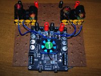
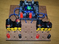
I built the new filter last night according to the diagram below and listened to it this morning after letting it burn in overnight. I wound my own air core coils to 3.86uH out of unwound 20ga close out coils I bought just for the wire, according to the calculator here.
http://www.captain.at/electronics/coils/
17 turns, 21.35mm diameter, 24mm length.
The caps are pairs of .47uf Dayton foils giving .94uf. I used 6 parallel, 10 ohm 1/8 watt metal film resistors because that's what I had, to get 1.66 ohms. I purchased 2 Sure amp boards when I ordered so as to be able to do A B comparisons of mods as I went but one amp never played the right channel and the left may be weak so I am left doing comparisons to my main amp. The first amp I ever built. TDA7250 driver with cheap TIPs for the output. I've been using it for 8 years and always looking for something better. I'm still looking. The Tripath is a marvel of efficiency and multiple channels can be run off of a $25 psu opening the door to a really crazy 5 way digital active cross speaker I have been waiting to build. I was really exited when I first plugged it in to hear how good it really was and even hoped that with a few mods it might actually surpass the sonics of my other amps. The input caps went first. I relaced them with 2 dayton foil caps paralleled for 1uf. This does give a worthwhile improvement in transparency. Every serious 2X100 owner will want to do this. Not having another stock board to compare to makes it harder to know what the changes are but this is easy enough to hear. Next in the discard bin went the input protection zeners? under the RCAs. It's hard to tell without another 2X100 but I didn't hear much difference. I would probably leave those on unless you are sure there is an improvement. I was really hoping that going to a smaller air core coil and better caps in the filter would really open up the fine detail but it didn't make the night and day difference I was hoping for. Not as much improvement as the input cap. Maybe just a little different. I will get a better idea if I can get Sure to replace my non functional board. I also tried running the fan on batteries and think it might have sounded slightly better. Again, having another amp would help.
As good as I can get it? I would still like to hear two boards with separate power supplies for left and right, and see if a 6 amp switcher might sound better than my linear supply or even drag some car batteries in. As it stands, the modified Sure 2X100 has great highs, triangles and bells sound very clean and articulate. It has a nice warm, ripe mid bass and decent power. The 7250 throws a deeper soundstage and has much better fine resolution all through the midrange. It allows you to hear the decay of reverberant tails much better. You can really hear more of the emotion and artistry of the players. And more of the natural sound of the space they were in. I was really pulling for the Sure because of the great price and efficiency but I'm afraid the search must go on. There's still nothing like a hot running, high bias class AB amp. Now I have to try the CP Designs modules. National Semi driver chip pushing the latest mosfets for $40 per channel.
.
Thank you, ElFishi, for the nice article. I don't fully understand it but I am getting a better idea of output filters.
If I understand correctly, what's known as "common mode filter with damping resistors" in the article seems to be the design to go for if I am willing to spend a little more on the multiple film capacitors required by it.
Can you guys check if I have understood correctly and have made correct calculations? I tried to come up with the values to be used for the inductors, capacitors and registers for this design by following the article.
I am assuming cut-off frequency of 80KHz as written in the Tripath manual and Speaker Load resistance of 4Ohm (for my speakers)
The optimum value for the filter inductor is L = RL/2pi fc, according to the article so this gives me the L value of 7.968127 uH , or about, 8uH
But since the total inductance is divided between two inductors,
L1 = L2 = ½L = RL/(4 pi fc) = about 4uH
And the capacitors are
C1 = C2 = C3 = C4 = 2/((2pi fc)2 • L) = 1/((2 pi fc)2 • L1) = 0.98946uF or about 1uF
and
R1 = R2 = 1/(√2 • 2pi fc C1) = 1.4067442 = about 1.4 Ohm
Am I understanding it correctly? Have I made the calculations correctly?
Attachments
I built the new filter last night according to the diagram below and listened to it this morning after letting it burn in overnight. I wound my own air core coils to 3.86uH out of unwound 20ga close out coils I bought just for the wire, according to the calculator here.
http://www.captain.at/electronics/coils/
17 turns, 21.35mm diameter, 24mm length.
.
"Air cores for class D are a big no-no unless..."
Last edited:
Thank you, Scott, for going through all the trouble of trying the filter and sharing your opinion with us. Thanks also goes to ElFishi for sharing the simulation result.
I have been reading more about Inductor core materials and shapes and starting to understand a little better why Tripath recommends Carbonyl-E iron powder core in Toroidal shape.
I was initially very confused because I misunderstood that "E" in Carbonyl-E referred to the shape of the inductor core such as E shape core, but then now I understand that "E" here refers to a specific composition of Carbonyl iron.
But then where do I get inductors made from Carbonly-E toroidal core with inductance of 11uH, high DC current rating, low max DCR and importantly small enough to fit four of them in the Sure board?
A lot of respect to those who can wind their own inductors, Scott and ElFishi!
BTW, I have found a following document by Jim Cox of Micrometals about selectiong Iron Powder Cores
http://www.lodestonepacific.com/distrib/pdfs/Micrometals/ipcs4rfp.pdf
Last edited:
Another output filter
ElFishi,
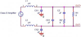
Could you kindly do a simulation on the following filter that I have attached and tell me whether they make any sense?
This is a simpler design I think I can try easily on the Sure board. In fact, it's from articles (Class D Faq Part I and II) on the same site you mentioned last time (www.audiodesignline.com)
I am planning to use the following values:
Assumed cut-off frequency: 80KHz (as per Tripath recommendation)
Speaker Load: 8 Ohm (my new speaker)
L1 = L2 = 11uH
CD1 = 0.15uF
CS1 = CS2 = 0.015uF
CZ = 0.22uF
RZ = 8 Ohm
The total capacitance from CS1+CS2+CD1*2 is somewhat less than the one calculated based on the formula given in the article, but I am using them because these values seem to be more readily available. The same goes for the CZ value. (it should be 0.2486795... according to the formula)
I am also taking a recommendation in another document which says the "shunt" capacitors must be about 10% of the differential capacitor.
I would very much appreciate your time and help if you could do a simulation on it. Thank you very much in advance!
ElFishi,
Could you kindly do a simulation on the following filter that I have attached and tell me whether they make any sense?
This is a simpler design I think I can try easily on the Sure board. In fact, it's from articles (Class D Faq Part I and II) on the same site you mentioned last time (www.audiodesignline.com)
I am planning to use the following values:
Assumed cut-off frequency: 80KHz (as per Tripath recommendation)
Speaker Load: 8 Ohm (my new speaker)
L1 = L2 = 11uH
CD1 = 0.15uF
CS1 = CS2 = 0.015uF
CZ = 0.22uF
RZ = 8 Ohm
The total capacitance from CS1+CS2+CD1*2 is somewhat less than the one calculated based on the formula given in the article, but I am using them because these values seem to be more readily available. The same goes for the CZ value. (it should be 0.2486795... according to the formula)
I am also taking a recommendation in another document which says the "shunt" capacitors must be about 10% of the differential capacitor.
I would very much appreciate your time and help if you could do a simulation on it. Thank you very much in advance!
Attachments
I did get a hold of the printouts of the Bode plots from the filter simulation so I can post them here. I don't have access atm to the machine where I installed pspice to do the simulations. I'm using the student's version I picked up to download from somewhere in the web. It is simple enough to try for yourself. Cost me an hour or so to do the simulations I wanted. There are also turorials out there. If you have the patience I can run your simulation in a few days, swkbkk.
Attached is the schematic of the output filter I built.
C1 and C6 are the common mode capacitors, C_C,
C10 is the Zobel capacitor C_Z and
C7 is the differential mode capacitor, C_D,
R3 is the load where I used 4 Ohms throughout
Each bode plot has a header containing a filename that contains the values of the parts "left to right".
The first one is the one in the schematic, the second is what tripath recommends in the data sheet text, the third is what the sure board has fit and the last is the filter as posted by swkbkk.
Attachments
filters with part numbers known from another thread?
Doesn't it seem that all of this work would surely have been done already in another thread? The Tripath has been in use by modifiers for years. I would be surprised if there weren't coil recommendations at least.
Doesn't it seem that all of this work would surely have been done already in another thread? The Tripath has been in use by modifiers for years. I would be surprised if there weren't coil recommendations at least.
Thanks a lot for sharing your filter design and for offering to do the simulation for me, ElFishi. It would be definitely a good investment for me to teach myself how to do the simulation and know what they all mean. But I think it will take quite some time for a novice like me to get to grisp with it and I am not even sure if I am going to make any sense out of the output. I will probably start downloading the program and have a look at it soon, but I would still appreciate your help on this. Please take your time. Anytime you can manage a bit of free time, mate! Thank you so much in advance and I do really appreciate your help and time on this.
here you go
Speaker Load: 8 Ohm (my new speaker)
L1 = L2 = 11uH
CD1 = 0.15uF
CS1 = CS2 = 0.015uF
CZ = 0.22uF
RZ = 8 Ohm
Attachments
Thanks a lot, ElFishi, for taking time to do the simulation for me.
To be honest, I am not quite sure how to interpret the graph, but I take the graph's going upward at around 10Khz as a sign of being "not good".
I will definitely have to "study" a bit more to understand the implications of the graph.
Thanks again, ElFishi
To be honest, I am not quite sure how to interpret the graph, but I take the graph's going upward at around 10Khz as a sign of being "not good".
I will definitely have to "study" a bit more to understand the implications of the graph.
Thanks again, ElFishi
Is this not a great response, considering it's less than +1db @ 20kHz? Or is the point to have the knee @ 20Khz?
Last edited:
- Status
- Not open for further replies.
- Home
- Amplifiers
- Class D
- Sure Electronics New Tripath Board tc2000+tp2050