Hi everyone:
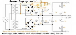
I've received so much help from you all on my Chipamp project, that I thought I'd make an (albeit small) contribution back. Here is a pic. of the Chipamp.com PSU with part numbers on top, as well as the LED power light indicator circuit and parts.
Hope this helps someone.
I've received so much help from you all on my Chipamp project, that I thought I'd make an (albeit small) contribution back. Here is a pic. of the Chipamp.com PSU with part numbers on top, as well as the LED power light indicator circuit and parts.
Hope this helps someone.
Attachments

scottjoplin:
I'm a total newbie with nearly zero electronics knowledge. If you would please clarify what you mean by that, I will try to fix the diagram.
I'm a total newbie with nearly zero electronics knowledge. If you would please clarify what you mean by that, I will try to fix the diagram.
Last edited:
scottjoplin:
Sorry, not clear. What do you mean by reverse? Do you mean swap label D3 with D8 and swap D7 with D4 or something completely different?
Sorry, not clear. What do you mean by reverse? Do you mean swap label D3 with D8 and swap D7 with D4 or something completely different?
Look at the two halves of the PSU - the same connections that give positive output on top give a negative output on the bottom 😀
Leave C6 and the other components as they are, but connect the D3/D7-node to the negative side of C6 and the D4/D8-node to the positive side.
/U.
Leave C6 and the other components as they are, but connect the D3/D7-node to the negative side of C6 and the D4/D8-node to the positive side.
/U.
Nisbeth:
I can't really imagine in my mind exactly how that would look. Maybe someone else can change the diagram and re-post?
I can't really imagine in my mind exactly how that would look. Maybe someone else can change the diagram and re-post?
Current only flows in one direction through a diode. Some of the diodes are drawn the wrong way and need to be reversed. This schematic keeps popping up with the same response.
Mark:
Thanks for that.
levistubby:
Yes, I know. I'm just trying to make it easier for newbies. It's never a great thing when a schematic doesn't match a PCB.
Thanks for that.
levistubby:
Yes, I know. I'm just trying to make it easier for newbies. It's never a great thing when a schematic doesn't match a PCB.
I think both the schematic and the PCB are correct. If you measure the DC at the outputs you’ll find the +/- orientation is exactly the same even though the outputs are marked (from left-to-right) as V+/PG+ then PG-/V- If you reverse the polarity of your probes you’ll measure the direct opposite polarity from the V/PG outputs on their respective sides. https://www.electronics-tutorials.ws/diode/diode_6.html
Will likely work better if the snubber components are connected closer (directly) to the rectifier diodes (source of hf shot noise) and not at the opposite end of the board, inches away from them and the added inductance of the filter capacitors as well.
Pretty nice to have a board with everything on it though, much cleaner looking than some of my setups!
Pretty nice to have a board with everything on it though, much cleaner looking than some of my setups!
Tom Christiansen (Neurochrome Audio) has just posted a very interesting article - Rectification and Snubbers, well worth a read.
Power Supply Design: Rectification & Snubbers.
Power Supply Design: Rectification & Snubbers.
Last edited:
That write up is odd to say the least, couldn’t figure it out really.
Starts out describing what happens, then claims it doesn’t matter...
I trust my ears and suggest that others do the same, could save yourself a lot of money and hassle possibly too it appears.
Starts out describing what happens, then claims it doesn’t matter...
I trust my ears and suggest that others do the same, could save yourself a lot of money and hassle possibly too it appears.
Not only do I claim that the addition of snubbers will not make any difference to the output of an audio amplifier, I validate that claim with measurements.
Adding a snubber might make a difference on whether your amplifier can pass the regulatory requirements for EMI, but that's another story.
Tom
Adding a snubber might make a difference on whether your amplifier can pass the regulatory requirements for EMI, but that's another story.
Tom
Not only do I claim that the addition of snubbers will not make any difference to the output of an audio amplifier, I validate that claim with measurements.
Adding a snubber might make a difference on whether your amplifier can pass the regulatory requirements for EMI, but that's another story.
Tom
Hello Tom,
Where is this post?
[edit, nevermind, I found it Taming the LM3886 Chip Amplifier: Rectification and Snubbers – Neurochrome ]
Thank you,
David.
Last edited:
- Home
- More Vendors...
- Chipamp
- PSA: Chipamp.com snubberized PSU schematic with part numbers