I've started designing my own amp.
The goals:
Be capable of pushing out 50W at 4Ohms
I wanna use the 3886 because its readily available and cheap.(its kinda weird that 3886 costs ~6 bucks and 3876 is whopping 15 and ppl guess what - noone has 3875 nor 1875 😕 )
PSU transformers are available from 20VA to 700VA, so thats not a big problem.
Couple of days I've been studying 3886's datasheet/googling and thinking how to get things done correctly, I've been studying the typical application circiut and tried to search for the schematics of amps using that IC and then the hell began - Inverted/Noninverted, Buffered/Unbuffered, and now I'm confused what to choose ?
The questions:
Why is the noninverted is better than inverted ?
Why is the inverted is better than noninverted ?
Why is the buffered is better than unbuffered ?
Why is the unbuffered is better than buffered ?
Can you answer in plain English ? (answer "because its sounds better" is not an option, comment it atleast )
Thanks.
P.S. And yeah I was like 😱 when I saw a price tag for a OPA627 - 48$ (TL072 is like 50ct) now thats a pretty darn expesive opamp, never thought those can cost THAT much ...
Picked up my tranny today, 100VA 2x24V with 2 full bridge rectifiers this gonna get me a nice 31V on each rail. I also think about putting caps on bridge diodes, as for filter caps I'll stick to 4-6 10000x35V (I'm not biulding a GC with 200VA tranny and 1k caps), they cost reasonably (for the cost of 1 22k I can have nearly 6 10k's). According to nationals formula for 50W @ 4ohms we need ~31V so we fit just right.
Doh, why do you choose inverted vs. non inverted ?
P.S. I've been reading "the best buffer for GC" thread and at the moment one thing is for sure OPA627 is out of the question 😀
Doh, why do you choose inverted vs. non inverted ?
P.S. I've been reading "the best buffer for GC" thread and at the moment one thing is for sure OPA627 is out of the question 😀
Try to use buffered version cos LM should work with less gain; in this case you have got better SR and BW.
Hi Vec70r (?),
The question of using inverted vs non inverted has been going on for a long time. It looks like it is system dependant . Like what chips you use and possibly a lot of other factors. With amps which have high distortion with common mode signals , the inverted scheme seems to work better as the inputs are virtually tied to ground ( theoretically).
Many people who have tried some chips like the Lm3886 and 3875 prefer the inverted mode sound . However this is not a conclusive statement as some prefer the non inverted mode.
Better you design the board so that you can configure it either way and decide which sounds better in your set up.
The best buffer for your gain clone ? read all the opinions ( based on real tests) and pick the one you think sounds right for you.
You mentioned an opamp . Are you eliminating tubes ?
The choice is vast and only you can decide what is best for yourself. Try out good low cost opamps also. They will be good but "may" not be better than some exotic varieties. With a good DIP socket you can easily test different chips. Keep the costs down to start with.
Have fun.
Cheers,
Ashok.
mandat said:Try to use buffered version cos LM should work with less gain; in this case you have got better SR and BW.
What about the noise of the preamp being amplyfied by the power amp? Isn't 200kHz good enough at 30db gain?
Best preamp is no preamp (for me) if you don't have impeance issues/missmatch, which is if you design it right on the first place and if you don't have to run many meters of interconnects. But if you like it with preamp more and want to just play around, go wild, sky is the limit.
/Greg
In most op-amps (and these power-amp chips are just big op-amps), the inverted configuration usually gives lower distortion.
This is because in the inverted mode, the chip sees no common-mode signal. In the non-inverting mode, the input to the chip is also the common-mode signal that the chip is seeing (the NFB will force the - input to track the + input).
The big problem with inverting mode is that the input resistor should really be fairly low to keep the output offset voltage low, and noise low. If the input resistor is 1k, (for example) then you will need an active input buffer to drive the signal into the power-amp.
In non-inverting mode, the input impedance can be much higher (approximately the value of the resistor from the + input to ground)
 Hm as for buffer I think not afrerall, in the future I want a triamped sys, so I'll biuld an active XO, therefore the amp will see the XO and loading/impedances arent going to be a problem( I think about Rod Elliots XO, Linkwitz-Riley, its outpus are buffered by opamps)., as for now I will feed the amp from the Behringer Ultrabass, whis outputs are buffered (there is a balanced and unbalanced output). The wiring will be short so balanced looks like overkill.
 I think I'll try inverted afterall, BTW I'll use trimpots for volume adjustment, I dont need it on the amp, I have a mixer (the DJ mixer).
Are you going to drive one or two channels off that 100VA torid?
Because if your driving two, it will be no where near enough.
For two channels at 50W out each, i would use a minimum of 250VA.
Because if your driving two, it will be no where near enough.
For two channels at 50W out each, i would use a minimum of 250VA.
My bass is on the another amp, so 100VA should be enough. Later I will build another one for bass, now there I'll put smthng around 160-230VA
This is what I came for at the moment. Inverting amp with 22x gain. Havent decided on the vol. regulator yet, I think about putting a trimmer instead of a pot, but what value ? mm 20K will be enough ? 
PSU and decoupling caps are not shown.
Do I miss something really important ? Ugh, do I need a resistor between the ground and the non-inverting input or I just connect non-inverting to the ground ?
PSU and decoupling caps are not shown.
Do I miss something really important ? Ugh, do I need a resistor between the ground and the non-inverting input or I just connect non-inverting to the ground ?
Attachments
VEC7OR said:
Do I miss something really important ? Ugh, do I need a resistor between the ground and the non-inverting input or I just connect non-inverting to the ground ?
Use some resistance or you will have offset.
You can try from 220K to 10K and see which works better for sound. Also listen to it with and without parallel cap on resistor.
Carlos
Your dc impedance from the - input to ground is 220k, (The input is capacitor-coupled so has an infinite dc impedance. To get the best thermal tracking of the dc offset you could put a 220k resistor from the + input to ground to match the dc impedance on both inputs.
My view is that 220k will increase the noise. Try it with a direct short from + to ground as you have at the moment. If the dc offset voltage is OK then you could leave it as it is.
(The other option is to put a 220k resistor, but bypassed with a capacitor.)
My view is that 220k will increase the noise. Try it with a direct short from + to ground as you have at the moment. If the dc offset voltage is OK then you could leave it as it is.
(The other option is to put a 220k resistor, but bypassed with a capacitor.)
The PCB, I'll use the laser printer and steam iron to transfer it to PCB, then peel the paper after its soaked in water and then I'll etch it 😀
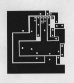
epp, tried that too, tried drilling them, now wanna try this, maybe even I'll try resist coated boards, but thats later on some bigger boards.
Hm, I wonder how good I'll be ? will the toner hold good ?
Hm, I wonder how good I'll be ? will the toner hold good ?
- Status
- Not open for further replies.
- Home
- Amplifiers
- Chip Amps
- Design from scratch (LM3886)