i've been watching a few youtube videos (like probably most of you), which were actually non audio related and noticed how many people seem to be getting PCB's and custom chips made, which made me think of has anyone done a small bt amp for a lowfi build?
i've bought a few CSR8645 Amplifier Boards and other variants of them (QCC3008) and due to the size find it difficult to firstly solder onto, but trying to cram it, plus a battery and a boost coverter all into a tiny build.
So my question would be, has anyone done a custom build, if yes, would it be hard to do for somebody who doesnt know how (but keen to learn) and how hard would it be to integrate something like a TP4056/7 1S BMS and a boost coverter (3.7 to 5v) etc?
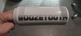
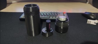
I have a few builds which are basically 3d printed 500ml beer cans with a downward firing 2inch full range and i want to use the amp as it has the ability to be modified through the BT chip and use custom EQ settings (and it is small).
example
Csr8635 dual 5w bluetooth 4.0 /4.1 amplifier board audio bluetooth 4.1 receiver module with call function Sale - Banggood.com
i've bought a few CSR8645 Amplifier Boards and other variants of them (QCC3008) and due to the size find it difficult to firstly solder onto, but trying to cram it, plus a battery and a boost coverter all into a tiny build.
So my question would be, has anyone done a custom build, if yes, would it be hard to do for somebody who doesnt know how (but keen to learn) and how hard would it be to integrate something like a TP4056/7 1S BMS and a boost coverter (3.7 to 5v) etc?
I have a few builds which are basically 3d printed 500ml beer cans with a downward firing 2inch full range and i want to use the amp as it has the ability to be modified through the BT chip and use custom EQ settings (and it is small).
example
Csr8635 dual 5w bluetooth 4.0 /4.1 amplifier board audio bluetooth 4.1 receiver module with call function Sale - Banggood.com
1)n it CAN be done
2) yiu ust leafn to design PCBs, which takes its time and efort
3) you must learn to design GOOD PCBs, so more time and effort
4) you must polish your skills, these circuits involving complex digital signals,very very high UHF frequencies, etc. are a new challenge.
5) you must learn to integrate all these building blocks into a functional unit.
6) that can possibly take Years.
7) so the *practical* solution to this problem is that you buy a couple Modules and practice soldering, maybe buy a lighted loupe, fine tipped soldering iron, long nose fine tip tweezers, etc. , practice makes perfect.

China Bench Type Repair Magnifier with LED Light 360 Degrees of Rotation 7023b Photos & Pictures - Made-in-china.com
2) yiu ust leafn to design PCBs, which takes its time and efort
3) you must learn to design GOOD PCBs, so more time and effort
4) you must polish your skills, these circuits involving complex digital signals,very very high UHF frequencies, etc. are a new challenge.
5) you must learn to integrate all these building blocks into a functional unit.
6) that can possibly take Years.
7) so the *practical* solution to this problem is that you buy a couple Modules and practice soldering, maybe buy a lighted loupe, fine tipped soldering iron, long nose fine tip tweezers, etc. , practice makes perfect.
China Bench Type Repair Magnifier with LED Light 360 Degrees of Rotation 7023b Photos & Pictures - Made-in-china.com
Last edited:
Yeeah ok, thanks JMFahey, i think i could be biting off more than i can chew considering i've never designed a PCB before. Maybe i should try googling to see if there are any proven designs first, or ones that could be purchased, although i think what im looking for could be a custom/unique thing and most probably wouldnt bother with it.
Custom chips??? You mean ASICs? Really?
I highly doubt that. One could go through a service like MOSIS but last I looked at their pricing (which was many moons ago) it was several $k per chip with a MOQ of 5. And that assumes you have the skills to design the chip and have licences for the software needed. A modern audio IC would be designed by a team of engineers (and others). Not by some dude in a basement somewhere. Maybe by many dudes in many basements...
As far as a lo-fi bluetooth gizmo goes, how about grabbing one of the many bluetooth-in, audio-out boards? Or bluetooth-to-I2S + DAC? That seems far more likely to succeed as a hobby project.
Tom
Just buy this and be done with it. If you want low Fi it’s not worth wasting your time making one from scratch.
TPA3116 50W+50W Bluetooth Amplifier Board Digital Audio Receiver TF Card U Disk Player Subwoofer With Remote for Speaker DIY|Operational Amplifier Chips| - AliExpress
Or this
https://a.aliexpress.com/_mLmkIeX
Or this
https://a.aliexpress.com/_mq3bznd
TPA3116 50W+50W Bluetooth Amplifier Board Digital Audio Receiver TF Card U Disk Player Subwoofer With Remote for Speaker DIY|Operational Amplifier Chips| - AliExpress
Or this
https://a.aliexpress.com/_mLmkIeX
Or this
https://a.aliexpress.com/_mq3bznd
Last edited:
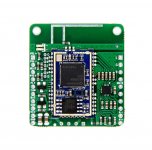
I actually have this one....
I'm able to access the Bluetooth module and change the EQ and name etc, which the board is 35*30mm and puts out (apparently) 5 watts a channel, found a step up module and integrated 1S BMS which is about the 2/3rds the size as the amp so it will do.
Just need to find a good EQ setting to compensate for a 2inch driver in a 0.015cuft beer can to lift the bottom end without burning through the 18350 battery (1200mah) which I the next challenge
Attachments
Yeeah ok, thanks JMFahey, i think i could be biting off more than i can chew considering i've never designed a PCB before. Maybe i should try googling to see if there are any proven designs first, or ones that could be purchased, although i think what im looking for could be a custom/unique thing and most probably wouldnt bother with it.
Careful layout can be vital.
1/ Use star grounding for anything taking current.
2/ Dont mix power supply smoothing cap ground with audio ground, join once at pcb edge connector.
3/ Keep high voltages and ac voltages away from audio signals.
4/ Keep transformers away from audio signals.
Fine pitch soldering is an art.
Line up IC on pcb and solder one pin carefully without moving IC.
I let solder on iron touch the pin but not the iron.
Add solder flux to pins.
Then drag solder along each side of the IC.
Any shorts can be got rid of by removing all solder from iron then dragging excess solder away from pin.
Any awkward bridges can be got rid of using copper de-soldering wick.
Its technique and a bit of practice.
Practice on a scrap pcb first.
Last edited:
- Home
- Amplifiers
- Chip Amps
- Anyone done a custom PCB for a small low fi BT/AMP before?