Hi,
This is possibly similar to LM3886 - getting hot - low volume
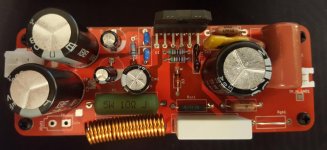
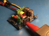
I've soldered up my LM3886 board and getting a hot chip (using a bad heatsink, if I use pliers to press it against a big heatsink then doesnt get hot).
The main issue I have is that it's apparently outputting 0v at the output with no load connected, and PC line output connected as input with no input attenuation via a volume potentiometer.
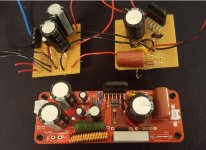
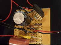
I had previously built a veroboard version (minus the zener mute function, minus the thiele and zobel networks) and that used the same bad heatsink and worked and had no heat issues.
This is a different chip - when I get time, I will swap the chips to see if I have a faulty one.
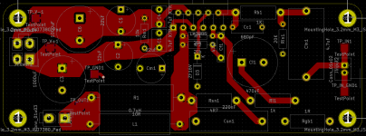
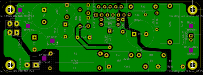
I'm using a pcb this time for the new amp, components are more compact compared to veroboard.
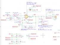
Rgb1 on the schematic is just a bit of hookup wire that has not been soldered - intent to use 1ohm 1w resistor. This might be causing issues, although continuity seems fine on those points, it might be introducing noise.
Anyone able to point me to the right direction please?
This is possibly similar to LM3886 - getting hot - low volume
I've soldered up my LM3886 board and getting a hot chip (using a bad heatsink, if I use pliers to press it against a big heatsink then doesnt get hot).
The main issue I have is that it's apparently outputting 0v at the output with no load connected, and PC line output connected as input with no input attenuation via a volume potentiometer.
I had previously built a veroboard version (minus the zener mute function, minus the thiele and zobel networks) and that used the same bad heatsink and worked and had no heat issues.
This is a different chip - when I get time, I will swap the chips to see if I have a faulty one.
I'm using a pcb this time for the new amp, components are more compact compared to veroboard.
Rgb1 on the schematic is just a bit of hookup wire that has not been soldered - intent to use 1ohm 1w resistor. This might be causing issues, although continuity seems fine on those points, it might be introducing noise.
Anyone able to point me to the right direction please?
Attachments
-
 Screenshot_20210414_014935.png26.6 KB · Views: 515
 -
 Screenshot_20210414_015102.png63.4 KB · Views: 517
 -
 Screenshot_20210414_015113.png63.2 KB · Views: 502
 -
 Screenshot_20210414_020401.jpg80.6 KB · Views: 179
 -
 Screenshot_20210414_020347.jpg101.5 KB · Views: 199
 -
 Screenshot_20210414_020334.jpg120.1 KB · Views: 469
 -
 Screenshot_20210414_020320.jpg87.5 KB · Views: 503
Last edited:
If it runs cool with pliers, you need locking pliers? Or a proper heatsink screw?
I don't have any locking pliers. The good heatsink I have is part of the case enclosure I want to use, but I havn't decided yet where to position the boards, and without that decision, I wouldn't know where to drill the mounting hole for the LM3886.
Zero Volts DC is usually the expected output with no audio signal.
I've got the input connected to an audio signal playing music from a desktop computer, and the output is 0v and chip is getting hot.
Why is the ground jumper not soldered? Sounds like trouble.
It's a double sided board and I was holding off soldering it as I wasnt sure if my solder-sucker or wire wick would be good enough to remove the solder. I'll try with it soldered tonight.
Speakerground to powerground connection looks to be missing in both the schematic and board.
Speaker ground and power ground are connected directly to each other on the power supply board.
Would it be better to connect a short jumper wire under the power socket of the amp board so that power ground and speaker ground are shorted at the amp board as well?
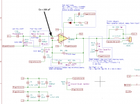
I think the issue is that you forgot the compensation cap (Cc) on the inputs of the LM3886 (see attached schematic) and the LM3886 is now oscillating. If you probe the output with a scope, I bet you'll find a nice signal there, probably in the range of 1-10 MHz. You'll probably find that Rsn1 is heating up too.
Adding flying parts is a bit annoying, but I bet a 1206 size surface mounted capacitor would fit nicely between the IC pins on the bottom of the board. KEMET P/N: C1206C221J5GAC7800 (Mouser P/N: 80-C1206C221J5GACTU) would be a good fit.
Nice work otherwise, though.
The best place to join the signal ground and speaker ground is at the speaker terminals. You can read more here: Taming the LM3886 Chip Amplifier: Grounding – Neurochrome
That said, I don't think grounding is your issue here. Your schematic looks right and the PCB layout is pretty decent, so the circuit should work as long as you have all three grounds connected together.
If you run the LM3886 on ±30 V without a heat sink, it'll definitely get warm. It'll probably get to 50-60 ºC case temperature. I've run it like that even with a signal applied to the amp. As long as you don't have a load connected, that should work just fine.
Once you connect a load, you will need a heat sink. I often use a 0.4 K/W heat sink (165 x 300 x 50 mm, 2 kg) for testing because I have some. For a quick test, I'll often use a Bessey spring clamp (see attached) to clamp the LM3886 to the heat sink. I can get full performance out of the LM3886 in that configuration.
If you go with those clamps, be a bit careful as the metal of the clamp tends to eat through the protective plastic tips. That makes it easy for the metal to contact the leads of the LM3886 with potentially disastrous consequences. Ask me how I know... When I go to replace my clamps, I'll get the more expensive ones with plastic jaws.
A PCB layout tip: If you set up your layout tool with the appropriate design rules for trace and pour spacing, you can just draw large rectangles (or polygons) for the pours. The tool will then figure out how to design the pours such that you get the specified minimum spacing between pours and traces. That'll save you a lot of hand drawing on those pours.
Tom
Adding flying parts is a bit annoying, but I bet a 1206 size surface mounted capacitor would fit nicely between the IC pins on the bottom of the board. KEMET P/N: C1206C221J5GAC7800 (Mouser P/N: 80-C1206C221J5GACTU) would be a good fit.
Nice work otherwise, though.
Speaker ground and power ground are connected directly to each other on the power supply board.
The best place to join the signal ground and speaker ground is at the speaker terminals. You can read more here: Taming the LM3886 Chip Amplifier: Grounding – Neurochrome
That said, I don't think grounding is your issue here. Your schematic looks right and the PCB layout is pretty decent, so the circuit should work as long as you have all three grounds connected together.
If you run the LM3886 on ±30 V without a heat sink, it'll definitely get warm. It'll probably get to 50-60 ºC case temperature. I've run it like that even with a signal applied to the amp. As long as you don't have a load connected, that should work just fine.
Once you connect a load, you will need a heat sink. I often use a 0.4 K/W heat sink (165 x 300 x 50 mm, 2 kg) for testing because I have some. For a quick test, I'll often use a Bessey spring clamp (see attached) to clamp the LM3886 to the heat sink. I can get full performance out of the LM3886 in that configuration.
If you go with those clamps, be a bit careful as the metal of the clamp tends to eat through the protective plastic tips. That makes it easy for the metal to contact the leads of the LM3886 with potentially disastrous consequences. Ask me how I know...
When I go to replace my clamps, I'll get the more expensive ones with plastic jaws.A PCB layout tip: If you set up your layout tool with the appropriate design rules for trace and pour spacing, you can just draw large rectangles (or polygons) for the pours. The tool will then figure out how to design the pours such that you get the specified minimum spacing between pours and traces. That'll save you a lot of hand drawing on those pours.
Tom
Attachments

Last edited:
Thanks for your reply Tom, and thanks for your kind words about my PCB layout (this and the psu boards are the first proper boards I've ever done). I've simply followed various advice of the very capable and smart people here and elsewhere.
I've got a 1042 (believe it's a 104 code, 100nF) cap that must be 20 years old, that I could try soldering onto the legs tonight.
I'm about to place an order on Amazon for a bunch of caps that also includes 220pF, to arrive tomorrow so I can try that too.
This might mean a board re-layout, but I want to see if I can get it working normally first.
Given that there's audio input present, and no output load, is it likely that the LM3886 oscillating will show up as 0V on the output?
Sadly I don't have a scope, so can only see the average reading of the (slowly responding) multimeter.
I'll solder up the signal to power ground wire tonight and see if I can inject the input signal directly to the Rb1 Rin1 junction, bypassing Cin1 to see if that has any difference.
If you place 100 nF between the inputs of the LM3886 it will oscillate for sure. You need something in the range of 150-220 pF. Those would be labelled 151, 181, and 221 (150 pF, 180 pF, 220 pF, respectively). Make sure you get one with C0G/NP0 dielectric. The other dielectrics cause too much variation in capacitance as function of voltage and temperature to be useful as a compensation cap.
If the LM3886 is oscillating you'll have 0 V DC on the output, but some AC voltage present in the low MHz or high hundreds of kHz range. A good bench top multimeter can measure that. many handheld meters don't have that much bandwidth. They may show some AC voltage. They may not.
A quick thing you can try before adding the compensation cap is to take Rf2 or Cf1 out of the circuit. If the LM3886 still gets hot to the point where you can't touch it, it's probably not a stability issue.
Double check that the 20 kΩ resistors are indeed 20 kΩ (red-black-black-red-tolerance). They appear to be, but colours can be hard to judge in a picture with artificial lighting.
Tom
I did order a pack of ceramic caps from Amazon but these have no info on what dialectric they are and probably are useless for this purpose.
Still, might be worth a try?
Otherwise I'm looking at Mouser or RS and £12+ shipping just for a couple of capacitors.
As for a multimeter, I only have a cheap Laser 3533 unit, probably cost only £5. Not prepared to buy a replacement yet as I'm saving up for a Fluke or equivalent.
Last night's test didn't show up Rsn1 to be hot, as you suggested in reply earlier. But Rf1 and Rb1 were slightly hot, possibly only due to their proximity to the chipamp.
Still, might be worth a try?
Otherwise I'm looking at Mouser or RS and £12+ shipping just for a couple of capacitors.
As for a multimeter, I only have a cheap Laser 3533 unit, probably cost only £5. Not prepared to buy a replacement yet as I'm saving up for a Fluke or equivalent.
You'll probably find that Rsn1 is heating up too.
Last night's test didn't show up Rsn1 to be hot, as you suggested in reply earlier. But Rf1 and Rb1 were slightly hot, possibly only due to their proximity to the chipamp.
Are there no other shops for electronic components in the UK? If not I am sure you can find something suitable on eBay. Whenever I look for electronics stuff on eBay (for whatever reason that might be) there are lots of offers from the UK. Just search "1206 SMD Capacitor" and you should find what you are looking for. For example this offer.
I think the issue is that you forgot the compensation cap (Cc) on the inputs of the LM3886 (see attached schematic) and the LM3886 is now oscillating. If you probe the output with a scope, I bet you'll find a nice signal there, probably in the range of 1-10 MHz. You'll probably find that Rsn1 is heating up too.
I didnt have this issue on the Veroboard version, and I didn't have the compensation cap on that version either.
Measurements when unpowered:
Rf2 = 19.97 k measured
Rf1 = 19.98 k measured
Rin1 = 19.06 k measured
Rb1 = 1.00 k measured
Ri1 = 1.00 k measured
Powered up and attached (badly) to a big heatsink, it doesnt seem as hot, but still gets hot and the output pins seem to have a few milivolts that are fluctuating, cant tell if this is the input signal or oscillations, but I suspect oscillations as suggested by an earlier reply.
I'm not sure I have space or if I am good enough to try smt capacitor in such a small space.
I've removed the LM3886 from the veroboard, unsure if I should attempt removing the one that's in the PCB and swapping them around.
Looking at this: Taming the LM3886 Chip Amplifier: Stability – Neurochrome
suggests that my Ri1 and Rf1 should be really close to the LM3886, however my Ri1 is off towards the edge of the board. Is this likely to be causing my issues? I can't get anything significant out of the amp.
I've tried desoldering Rf2 as per previous suggestion and have failed to melt the solder inside the thru-hole, cannot get all the solder out and remove the component.
Shorted out the Zener diode. Put multimeter on Power ground : Pin 3.
On power on, the voltage splikes to +10V and drops off pretty quickly to 0.00, although I think at lower range it shows it as a few milivolts jumping about.
On power off, stays on 0v for a few seconds, then jumps to -5V or so, and quickly drops to -0.8v or so then slowly comes towards 0V.
On power on, the voltage splikes to +10V and drops off pretty quickly to 0.00, although I think at lower range it shows it as a few milivolts jumping about.
On power off, stays on 0v for a few seconds, then jumps to -5V or so, and quickly drops to -0.8v or so then slowly comes towards 0V.
With the zener shorted, you should have Rmute = 33 kΩ, Cmute = 100 uF. Your current values will work OK, but expect a turn-on pop. But this is not why the LM3886 gets hot.
If you have all the grounds (SignalGround, PowerGround, and SpeakerGround) connected together and include Cc (220 pF), the circuit should work. If it doesn't you either have a bad component or accidentally installed the wrong component.
Where did you buy the LM3886? If you bought directly from TI or from an authorized distributor (Mouser, Digikey, Farnell, RS, Newark, etc.) it is very unlikely that you received a dead one. They are hard (but possible) to kill with electrostatic discharge, though.
The easiest way to desolder components from a through-plated board is to cut the lead on one side, heat it up from the other, and pull it through while the solder is still molten. Then use a solder sucker or solder wick to clean out the hole.
Tom
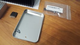
So I decided to conduct a little experiment for you. I powered my LM3886DR by a pair of HP 6643A lab supplies set to provide ±30 V. The LM3886DR had no input (so input grounded by 48 kΩ) and no load. I measured the temperature on the back side of the LM3886TF package with an infrared thermometer (the red tip you can see in the picture).
On ±30 V, the LM3886DR drew 52 mA from the supply and the back of the IC package reached 80 ºC.
On ±35 V, the LM3886DR drew 53 mA and the back of the IC package reached 95 ºC.
You might be able to glean some insight from measuring the supply current. If your ammeter can't resolve low currents, insert 10 Ω in series with each power supply lead and measure the voltage across these resistors.
Tom
Attachments
I might have been an idiot with my readings of the voltages.
I'm getting a turn-on pop and another at turn off, and this is with the Zener diode.
The DC voltage spikes to approx +8V and settles to 0 on turn on.
There is a turn off spike -4V approx and settles fairly quickly to -0.68V where it slowly discharges.
I've crudely soldered the 220pF cap on the bottom of the board directly onto pins 9 and 10, before taking any of the measurements mentioned in this post.
Bought it from RS.
LM3886TF/NOPB Texas Instruments, Audio Amplifier 8MHz, 11-Pin MLPP
Stock no.:534-2961
Wonderful, thanks for the tip
So I did more poking around and have some voltages. I appear to have been an idiot (and I also really need a better multimeter) and measured DC voltages in my previous posts, when I should have measured AC for the output and presumably also the voltages on the pins 3, 9, and 10.
Measurements with no load and no input:
Pin1: +38V DC
Pin2: 0V DC
Pin3: 0V DC
Pin4: Could not measure - caused a spark as my probes touched pin 3 at the same time.
Pin5: +38V DC
Pin6: did not measure
Pin7: 0V DC
Pin8: -4V DC
Pin9: -2V DC (I though this changed to 0V DC on another reading but I didnt record it on my piece of paper)
Pin10: -1.9V DC
Pin11: did not measure
Voltage across the Zener: 15.7V DC - this seemed odd as it was supposed to be rated for 16V. I will consult a book.
Voltage across Rm1 (mute resistor): 17.89V DC
Speaker output: 0.3V apparently DC, this is on the "200m" range setting on multimeter which seems smaller on the dial than the "2000m" range, which confuses me.
Speaker current: 0A apparently.
Did not get to measure the current drawn from VCC and VEE - for another day.
Measurements with input:
400Hz sine wave tone set to "0.9" intensity in Audacity and output on the Line Out connector on front of PC appeared to produce a 0.2V AC signal. I can't be sure if this is accurate given my poor test equipment.
Speaker output appeared to be 9.9V AC, which is mighty puzzling as I would say this represents a gain of 49.5, instead of the 21 that should be there given the components used (Ri1 = 1k, Rf1 = 20k, non-inverting setup). I've no explanation for this. I'm really confused.
DC output offset seemed to be odd, no doubt due to my instrumentation:
20 range on DMM: 0.05V
2000m range: +-6
200m range: +- 6
DMM is a Laser 3533, one of those cheapies you get from auto-parts places like Halfords.
Chip got hot, but that's understandable due to the small and thin heatsink currently used. The heatsink that will form part of the case should be better and larger (9.35 inch long * 2.5 inch high * 2.3 inch thick including fins, which are 30 fins, 2mm thick fins).
Sadly, I don't have a temperature sensor to check.
At this point, I'm unsure whether this is safe enough yet to plug in a speaker for a test. I'd like to find out if the turn on / turn off spikes are likely to be dangerous to any speakers I connect.
Any guidance for the next steps please?
With the zener shorted, you should have Rmute = 33 kΩ, Cmute = 100 uF. Your current values will work OK, but expect a turn-on pop. But this is not why the LM3886 gets hot.
I'm getting a turn-on pop and another at turn off, and this is with the Zener diode.
The DC voltage spikes to approx +8V and settles to 0 on turn on.
There is a turn off spike -4V approx and settles fairly quickly to -0.68V where it slowly discharges.
If you have all the grounds (SignalGround, PowerGround, and SpeakerGround) connected together and include Cc (220 pF), the circuit should work. If it doesn't you either have a bad component or accidentally installed the wrong component.
I've crudely soldered the 220pF cap on the bottom of the board directly onto pins 9 and 10, before taking any of the measurements mentioned in this post.
Where did you buy the LM3886? If you bought directly from TI or from an authorized distributor (Mouser, Digikey, Farnell, RS, Newark, etc.) it is very unlikely that you received a dead one. They are hard (but possible) to kill with electrostatic discharge, though.
Bought it from RS.
LM3886TF/NOPB Texas Instruments, Audio Amplifier 8MHz, 11-Pin MLPP
Stock no.:534-2961
The easiest way to desolder components from a through-plated board is to cut the lead on one side, heat it up from the other, and pull it through while the solder is still molten. Then use a solder sucker or solder wick to clean out the hole.
Wonderful, thanks for the tip
So I did more poking around and have some voltages. I appear to have been an idiot (and I also really need a better multimeter) and measured DC voltages in my previous posts, when I should have measured AC for the output and presumably also the voltages on the pins 3, 9, and 10.
Measurements with no load and no input:
Pin1: +38V DC
Pin2: 0V DC
Pin3: 0V DC
Pin4: Could not measure - caused a spark as my probes touched pin 3 at the same time.
Pin5: +38V DC
Pin6: did not measure
Pin7: 0V DC
Pin8: -4V DC
Pin9: -2V DC (I though this changed to 0V DC on another reading but I didnt record it on my piece of paper)
Pin10: -1.9V DC
Pin11: did not measure
Voltage across the Zener: 15.7V DC - this seemed odd as it was supposed to be rated for 16V. I will consult a book.
Voltage across Rm1 (mute resistor): 17.89V DC
Speaker output: 0.3V apparently DC, this is on the "200m" range setting on multimeter which seems smaller on the dial than the "2000m" range, which confuses me.
Speaker current: 0A apparently.
Did not get to measure the current drawn from VCC and VEE - for another day.
Measurements with input:
400Hz sine wave tone set to "0.9" intensity in Audacity and output on the Line Out connector on front of PC appeared to produce a 0.2V AC signal. I can't be sure if this is accurate given my poor test equipment.
Speaker output appeared to be 9.9V AC, which is mighty puzzling as I would say this represents a gain of 49.5, instead of the 21 that should be there given the components used (Ri1 = 1k, Rf1 = 20k, non-inverting setup). I've no explanation for this. I'm really confused.
DC output offset seemed to be odd, no doubt due to my instrumentation:
20 range on DMM: 0.05V
2000m range: +-6
200m range: +- 6
DMM is a Laser 3533, one of those cheapies you get from auto-parts places like Halfords.
Chip got hot, but that's understandable due to the small and thin heatsink currently used. The heatsink that will form part of the case should be better and larger (9.35 inch long * 2.5 inch high * 2.3 inch thick including fins, which are 30 fins, 2mm thick fins).
Sadly, I don't have a temperature sensor to check.
At this point, I'm unsure whether this is safe enough yet to plug in a speaker for a test. I'd like to find out if the turn on / turn off spikes are likely to be dangerous to any speakers I connect.
Any guidance for the next steps please?
I think picking up a used Fluke 70-series or 80-series could be a good start... Or maybe one of Fluke's "down-market" brands like AmProbe.
An 8 V turn-on transient would create a significant plop. The transient is likely higher as your meter is probably pretty slow to respond. I would try replacing Rmute with 33 kΩ and short out the zener diode. If you intend to run with the ±38 V power supply permanently, you could even up it to 39 kΩ.
The worst case DC offset should be within ±10 mV. Typically it's around ±2 mV.
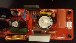
At ±38 V, the chip will get hot. Your heat sink sounds like it's big enough, though. A picture would be nice... Are you using any thermal grease between the IC and the heat sink? Are you using the insulated LM3886TF or the metal-back one (the LM3886T)?
Tom
An 8 V turn-on transient would create a significant plop. The transient is likely higher as your meter is probably pretty slow to respond. I would try replacing Rmute with 33 kΩ and short out the zener diode. If you intend to run with the ±38 V power supply permanently, you could even up it to 39 kΩ.
The worst case DC offset should be within ±10 mV. Typically it's around ±2 mV.
At ±38 V, the chip will get hot. Your heat sink sounds like it's big enough, though. A picture would be nice... Are you using any thermal grease between the IC and the heat sink? Are you using the insulated LM3886TF or the metal-back one (the LM3886T)?
Tom
I think the issue is that you forgot the compensation cap (Cc) on the inputs of the LM3886
Tom
On a tda7294 chip amp I used it needed that capacitor if the gain was reduced below a certain level. At low gains they can become unstable.
My amp was a valve/tda7294 and when the tda oscillated it radiated back into valve ! so I had a good RF oscillator.
The cap fixed it.
On the LM3886, the Cc = 150-220 pF cap across the inputs tame some parasitic oscillation that occur when the VAS exits saturation (i.e., near clipping). The added Cf = 47 pF and Rf2 = 20 kΩ clean up the transient response (Cc causes some peaking there).
You can run the LM3886 without Cc, Cf, and Rf2, but you get better performance when you include them. If you choose to include them, include all three components.
Tom
You can run the LM3886 without Cc, Cf, and Rf2, but you get better performance when you include them. If you choose to include them, include all three components.
Tom
I think picking up a used Fluke 70-series or 80-series could be a good start... Or maybe one of Fluke's "down-market" brands like AmProbe.
Is a Fluke 115 good enough? Or do you mean a Fluke 77?
Will try a 33k or a 39k when I get the chance, ordered some selection of resistors to arrive tonight.An 8 V turn-on transient would create a significant plop. The transient is likely higher as your meter is probably pretty slow to respond. I would try replacing Rmute with 33 kΩ and short out the zener diode. If you intend to run with the ±38 V power supply permanently, you could even up it to 39 kΩ.
The worst case DC offset should be within ±10 mV. Typically it's around ±2 mV.
I think +-38V is may be too much, and may replace the 25V-0-25V toroid with an 18V model.
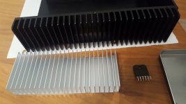
At ±38 V, the chip will get hot. Your heat sink sounds like it's big enough, though. A picture would be nice... Are you using any thermal grease between the IC and the heat sink? Are you using the insulated LM3886TF or the metal-back one (the LM3886T)?
LM3886TF is what I have.
I've got a new aluminium heatsink to play with and some thermal paste.
I'll include the old sheet metal heatsink in the picture.
Attachments
- Home
- Amplifiers
- Chip Amps
- LM3886 getting hot and 0v at the output