Either will work. If money allows, the 115 will be all the meter you'll ever need.Is a Fluke 115 good enough? Or do you mean a Fluke 77?
I think +-38V is may be too much, and may replace the 25V-0-25V toroid with an 18V model.
2x22 VAC (22-0-22), 150-200 VA would be my recommendation. That'll give you about ±30 V rectified. Maybe a bit higher without load.
The black heat sink should be plenty. The clear anodized one looks to be pretty thin on the base.
Tom
I did some calculations of the mute resistor as the voltage drops on power-off, and I think I agree with you that a larger resistor would be worth trying. I have a 30k ready which should start to mute at approx 17.6V supply.
I will try that when I get the chance.
I was thinking also for the feedback resistor, do I need to make sure it is > 1/4W? The op-amp (or chipamp lm3886 here) should have high input impedance, so I'd have thought not much current would flow through the feedback resistor from the output pin to the inverting input pin. Is my assumption correct?
I replaced the 10k mute resistor with 30k and shorted out the Zener for the mute.
This seems to eliminate pretty much all the power on / power off DC voltage spikes.
I'm not really sure why though. On power-off, I could understand that the mute cap would still hold charge and thus conduct through the zener, but I dont quite understand on turn-on after cap is discharged.
Sounds nice: Lm3886 chipamp Serj version 0.1 - YouTube
Any critiques or suggestions for the next step?
Last edited:
I replaced the 10k mute resistor with 30k and shorted out the Zener for the mute.
This seems to eliminate pretty much all the power on / power off DC voltage spikes.
Yay!
I'm not really sure why though.
I can see two possibilities:
- The mute pin is effectively floating on startup as the zener does not conduct. The LM3886 might not appreciate that.
- The zener current is pretty low, which means that you don't get the full zener voltage developed across the zener diode.
If option 2, try a low-current zener. You can get zener diodes that'll work at 50-100 nA (and some down to 5 nA too).
I've never quite understood why people add the zener diode. I mean, I understand what they're trying to do, but it's utterly unnecessary. Just use an RC and be done. Design for ~1 mA mute current at the nominal rail voltage.
If you absolutely want to keep the LM3886 muted until the supply voltage exceeds ±10 V, I think a better option would be to have a transistor pulling the mute pin to ground until the supply voltage exceeds ±10 V. Ideally you would design the circuit such that the LM3886 is held in mute if the positive supply is missing. I do that in the Modulus-286 and Modulus-686 as parallel LM3886es can show some undesirable behaviour if the IC is un-muted without the V+ supply.
Tom
Last edited:
Thanks for that explanation Tom.
I've been doing testing with the zener shorted and seems fine.
I dont really recall much of a pop now on turn-off / turn on either. More an instant-on with no pop, and a delayed off with no pop.
The Zener is a 1N4745ATR, and the datasheet says 5uA Zener current, this being too small?
Perhaps a future revision would involve the transistor setup as you suggest. For the moment, this may be "good enough". As I get more test gear in the months to come, then it may be a good idea to revisit.
The current update is:
- I've got something that plays.
- the heatsink is lukewarm when playing for 10+ minutes on medium volume.
- I think I did kill my tweeters though - no scope to check but perhaps an earlier version caused oscillations. Cheap PC speakers, maybe they were dead a long time ago.
- when no source connected to the RCA, there's a buzz / hum that gets louder as i increase volume. I know my pot is a bit dodgy so will replace it, but I'm worried there's a ground loop issue somewhere. With volume to 0, there's no buzz. Unsure what this could be - perhaps just RF or magnetic noise being picked up by the test wires and test pot?
- plugging in audio source (PC line out) while amp is turned on causes pops and bzzzz noises, when no sounds playing. Same if I hold the jack plug on the cable that goes to the RCA - is this normal (noise picked up during mechanical plugging in) or some sort of filtering / grounding issue? (EDIT: when plugged in, and sound playing, there's no pops etc. Just the moment when plugging in)
Last edited:
The Zener is a 1N4745ATR, and the datasheet says 5uA Zener current, this being too small?
That should be fine. If you have an oscilloscope it could be interesting to measure the zener voltage during startup. That's more of academic interest at this point, though.
I've got something that plays.
Sweet! That was the goal, right? 🙂
when no source connected to the RCA, there's a buzz / hum that gets louder as i increase volume.
That's normal. You're picking up mains hum and noise as the amp's input is terminated in the relatively high input impedance (Rin1 = 20 kΩ).
With volume to 0, there's no buzz.
Then you have no ground loop - or if you do, it's not of any consequence.
plugging in audio source (PC line out) while amp is turned on causes pops and bzzzz noises, when no sounds playing.
Also normal. Your body acts as a great antenna for all sorts of hum, which the amp will happily amplify. This is why we don't mess with the interconnects when the amp is powered up and connected to speakers. 🙂
Tom
Its important with amplifiers to get the earthing right.
One earth is good in the total system.
None or more than one earth can cause hum.
If the input is floating and volume control open you will pick up whatever is floating around like mains fields and RF.
Screening the input audio can help.
Many amps have RF filters on the front end.
One earth is good in the total system.
None or more than one earth can cause hum.
If the input is floating and volume control open you will pick up whatever is floating around like mains fields and RF.
Screening the input audio can help.
Many amps have RF filters on the front end.
I have a high-pass, low-pass arrangement at the input, not sure if the design could be better - it wasnt my design, i'd have to do more learning to get to that level.
I do now have some serious speakers that arrived today, and i'm listening with just the 0.1 revision of the board, in mono single channel and is awesome!
I've got the 0.2 revision boards soldered up, just need to do some wiring / connector work and test with old speakers to make sure no issues with it. But this so far looks like it's working really well, and a great little Lockdown project.
I think as I go along, improvements will be with PSU to add snubbers, maybe better input filtering as you say, and some mute improvements as tomchr suggested. And perhaps a tone control pre-amp - really doesnt need any more gain for what I need it for, but would like to reduce the bass at night so I dont annoy the neighbours.
And of course, need to put into enclosure with fittings etc. That's the next challenge.
My previous comment about killing my tweeters... well, that seems to be a red herring - the tweeters on the old speakers are just for appearance, it looks like some painted metal or something, there's no tweeter speaker in the old box - that's some Arion Legacy 2.1 speakers I've been using for a few years. Good to be moving away from them.
It's playing a few songs now on medium-low volume into 80s Mordaunt-Short MS35Ti and aluminium heatsink is just lukewarm.
Hard to tell without a scope, but the Brymen BM235 DMM in DC mA range showed one or two short spikes of approx 1.4mA DC while observing for a few minutes listening to Phil Collins - In The Air Tonight at a fairly low volume to not upset neighbours 🙂
All the other readings were somewhere in the 0.7-0.2 mA DC.
All the other readings were somewhere in the 0.7-0.2 mA DC.
Hi
For measurements of DC offset a Multi meter is needed....not more
amp is powered on, no speakers connected
no signal, connection to your source or both RCA connectors are shorted
then measure with Multimeter the DC offset at your speakers terminals
chris
For measurements of DC offset a Multi meter is needed....not more
amp is powered on, no speakers connected
no signal, connection to your source or both RCA connectors are shorted
then measure with Multimeter the DC offset at your speakers terminals
chris
Chermann,
Thanks for the feedback, very useful info to help me test this.
The revision 0.2 board gives a pretty stable 0.1mA DC.
The 0.1 board gives a fluctuating reading < 1mA DC.
Thanks for the feedback, very useful info to help me test this.
The revision 0.2 board gives a pretty stable 0.1mA DC.
The 0.1 board gives a fluctuating reading < 1mA DC.
STOP !
you mean mV...not mA _DC! hopefully
please do not use the Multi meter as A-meter and go to the speaker terminals - you short the Output!
the multi meter has to be at Volt
chris
you mean mV...not mA _DC! hopefully
please do not use the Multi meter as A-meter and go to the speaker terminals - you short the Output!
the multi meter has to be at Volt
chris
Whoops, insufficient coffee problem.😱
It was indeed mV DC in my posts, not mA DC.
Thanks for raising this, that was a bit sloppy of me, apologies.
It was indeed mV DC in my posts, not mA DC.
Thanks for raising this, that was a bit sloppy of me, apologies.
With everything connected, and no audio playing (paused), I do hear a low volume buzz, possibly mains buzz.
No buzz when volume control turned down to 0.
My input wires from RCA to volume pot, to the LM3886 boards are unshielded, so maybe is that? I do have some shielded wires that arrived recently so will re-wire everything at some point in the next few days.
No buzz when volume control turned down to 0.
My input wires from RCA to volume pot, to the LM3886 boards are unshielded, so maybe is that? I do have some shielded wires that arrived recently so will re-wire everything at some point in the next few days.

Try shorting the RCA connectors. I.e. connect the shell to the centre conductor. I bet that hum/hiss will go away.
If the hum/hiss does go away the source is the issue. Try with the volume control at about 2 o'clock as that tends to be the worst case spot. 2 o'clock is roughly -6 dB and that's where the pot has the highest output impedance.
Tom
If the hum/hiss does go away the source is the issue. Try with the volume control at about 2 o'clock as that tends to be the worst case spot. 2 o'clock is roughly -6 dB and that's where the pot has the highest output impedance.
Tom
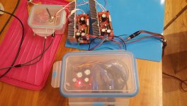
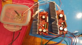
Slow progress here.
Some things done:
This project has come a long way since my first prototype last year.
Perhaps I should start a build thread?
Some things done:
- Made rear panel, but got the size wrong for the RCA connectors, so will need to get factory to make again.
- Bought a new pot (the Alps blue is smoother than the old one), and made a breakout board, because I hate soldering wires to potentiometer pins.
- Playing with the layout of the case and the boards.
- New PSU board (that I've not tested yet), largely based on carlosfm's circuit.
- And a latching mains switch with LED indicator, that I might use for the front panel.
- I still need to order accurate mic so I can profile the sound output.
This project has come a long way since my first prototype last year.
Perhaps I should start a build thread?
Attachments
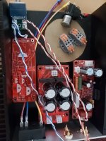
Nice work so far. Beware of the inrush current of the transformer. If you find that the mains switch wears out quickly you'll need to add a soft start.
I like the compact layout and that you use connectors rather than terminal blocks. It's also good to see heat shrink or boots on the mains terminals.
Tom
I like the compact layout and that you use connectors rather than terminal blocks. It's also good to see heat shrink or boots on the mains terminals.
Tom
- Home
- Amplifiers
- Chip Amps
- LM3886 getting hot and 0v at the output