View attachment 898330
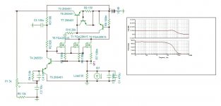
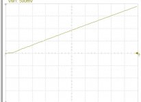
This what the simulator shows when I gradually decrease to zreo and then increase the supply. The signal first starts saturating then at 2.3V total supply strange things happen. Can someone confirm if this is the case in reality?
Something inside the triangle is not in mode
")
Difference of real OPamp from ideal.
Transient mode and steady state mode.
I added a jfet, any with Ivg0 over 20ma. To discharge the capacitors, it shorts the zeners. I will simulate with the single branch to see the result.
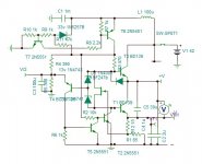
The main 42v regulator, I was hoping to find a ready made PCB of low impedance and fast, but my request on the relative forum remained silence. Dadod sells a very good one, but duel supply. So I decided once again deal with it myself.
An externally hosted image should be here but it was not working when we last tested it.
This is my floating Reactor commanding low cost triple mosfets. It is just a sketch to see how it performs. It has internal impedance of 0.01 ohms resistive up to 200khz. It requires only 100uF only output, Krell fbp200, much slower, has 8×47uF.
Attachments
Rush supply
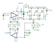
This much simpler version is better suited for this amp. It has an impedance of 0.015 ohm up to 20khz resistive. The mosfets have their TO220 versions as FQP.
An externally hosted image should be here but it was not working when we last tested it.
This much simpler version is better suited for this amp. It has an impedance of 0.015 ohm up to 20khz resistive. The mosfets have their TO220 versions as FQP.
Attachments
With some adjustments, 800uF can have 0.01 ohm to 22khz. The 4ma ccs can be LM334 CLD diode. I only need to add a current limiter.
This is with current limiter 6.35A.
This is with current limiter 6.35A.
Attachments
Last edited:
Composite in parafeed

I got an Idea of making of making the feedback in deferential. I want to relate you that I tried in vain many times to bridge two LM3886. even with gain of 2.8 each driven by 2.5k to 10k center tap transformer, I always lost the fine high frequency character of the single amp. This why bridged yes, only if it is corrected in deferential. The idea is parafeed. the center point of the output provides halved error signal of two branches, by feedback to the inverter it can reduce the error by the half of the output gain. I fixed it arbitrarily to 9.
Now, I can try the composite circuit to see how disastrous I get. I made a preliminary adjustment to get the highest frequency possible.

As you can see above I reach 5Mhz perfectly stable to see the transient. This is The disaster
As you can see on 200ns scale, the amp has a considerable blindness at the start. You can compare with the error correction way. Here is 50ns scale.
Of course the distortion is just slightly higher if not equal to that of the opamp 0.00003%.I'll estimate more in details later.
Hayk
I got an Idea of making of making the feedback in deferential. I want to relate you that I tried in vain many times to bridge two LM3886. even with gain of 2.8 each driven by 2.5k to 10k center tap transformer, I always lost the fine high frequency character of the single amp. This why bridged yes, only if it is corrected in deferential. The idea is parafeed. the center point of the output provides halved error signal of two branches, by feedback to the inverter it can reduce the error by the half of the output gain. I fixed it arbitrarily to 9.
Now, I can try the composite circuit to see how disastrous I get. I made a preliminary adjustment to get the highest frequency possible.
As you can see above I reach 5Mhz perfectly stable to see the transient. This is The disaster
As you can see on 200ns scale, the amp has a considerable blindness at the start. You can compare with the error correction way. Here is 50ns scale.
Of course the distortion is just slightly higher if not equal to that of the opamp 0.00003%.I'll estimate more in details later.
Hayk
Attachments
Considering the distortion in composite.
The output runs at low gain hence the distortion is less than 0.01% for gain of 9. The opamp runs in open loop, the gain is over 80db at 1khz, for most low distortion ones. If the given distortion for unity gain is 0.00003% than with open loop it becomes at least 10,000 times higher, that is 0.3%. As the two amps are in cascade than the distortions, if there is no cancelation, add up, 0.3%+0.01%. That is the distortion of the power stage becomes negligible. The feedback that opamp recieves is slightly higher than unity 0db as the power stage has a gain of 9.2 and reduced by 8.5 to adjust the total gain, it results 1.08. this means the added distortion by the power is decreased back to result the same overall closed loop distortion of the amplifier, 0.00003%.
You can view from transient scope graph, that an amplifier can have ultra low distortion, to speak commercially, World class, high precision amplifier, with bad intelligibility, good for background music in dentist waiting rooms.
Last edited:
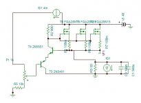
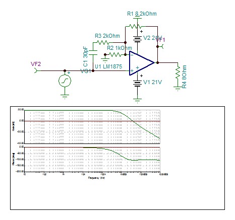
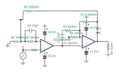
Here is a composite Quasi universal circuit as it can adapt any input opamp of your choice.

The inverter remains the same ultra fast AD8008 with +/-5V. Unconsidering for a moment power supply and small stability issues, I tried out several low distortion opamps. The other pair of AD8008, OPA637, OPA2134, LM4562 AND LME49710. If can suggest me other ones to try out, as there are so many that I ignore.
All graphs have 50ns scale. Classified from fastest to lowest. Of course AD8008 is the best but it is CFA bjt.
The AD8008

OPA637

LM4562

LME49710

OPA2134

The inverter remains the same ultra fast AD8008 with +/-5V. Unconsidering for a moment power supply and small stability issues, I tried out several low distortion opamps. The other pair of AD8008, OPA637, OPA2134, LM4562 AND LME49710. If can suggest me other ones to try out, as there are so many that I ignore.
All graphs have 50ns scale. Classified from fastest to lowest. Of course AD8008 is the best but it is CFA bjt.
The AD8008
OPA637
LM4562
LME49710
OPA2134
Last edited:
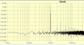
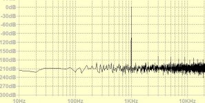
I measured the distortions on simulator of OPA627, LM4562 and AD8008 all unity gain 1k feedback resistors 1.5V input 100k ohm load.
1khz AD8008: 0.00008% , OPA627: 0.00002%, LM4562: 0.00002%
10khz AD8008: 0.0002% , OPA627: 0.0001% LM4562: 0.00013
Is it worthy to have a second opamp, than the AD8008 ?
1khz AD8008: 0.00008% , OPA627: 0.00002%, LM4562: 0.00002%
10khz AD8008: 0.0002% , OPA627: 0.0001% LM4562: 0.00013
Is it worthy to have a second opamp, than the AD8008 ?
I think you need to simplify the design and consider the costs in the light of the level of power the circuit will deliver. The composite amplifier in the link I provided gave $1 per watt at the time of publication of the article.
I have not looked to see how many devices are through the hole and how many are surface mount but you have multi voltages supplying the whole and each of them needs local decoupling. The composite amplifier partnered LM1875 with a precision FET input op.amp AD711/712 the price of these has been hiked. One can buy LM1875 in quantities of 5 for less than one LM1875.
OPA2134 has a more reasonable price tag - it may not be able to drive a 1k load as well as the others but you could cut some slack and increase the load resistance a little and save on some otherwise unnecessary expense.
The circuit layout has an influence on the THD figures in an actual build. It is good to see the back of the inductors you included in previous circuits - these could act as antennae for emi on supply lines or generated in the ether.
To function as parafeed inverter, AD8008 is a must. The power supply of 42V is high for all low distortion opamp, forcibly it needs extra regulated supplies. I am not troubling myself for cheap stuff but what best can be pulled out from LM1875 and best components it will get. It looks Bob Cordell's choice of LM4562, adopted by FF, is very good. I am thinking to put either the inverter as single AD8007 and the input opamp on socket to let the user choose his opamp, or have the input as AD8008 but straps or switches allows the user to disconnect internal opamp and plug in his choice.
The OPA2134 is out of the list, too slow.
Each LM1875 cost minimum 2$ if bought by 10pcs. the AD8008 is about 1$. The most cost is the power supply comparatively. Instead of having an armada of audio expensive capacitors, the low impedance supply is cheaper and higher performance.
The OPA2134 is out of the list, too slow.
Each LM1875 cost minimum 2$ if bought by 10pcs. the AD8008 is about 1$. The most cost is the power supply comparatively. Instead of having an armada of audio expensive capacitors, the low impedance supply is cheaper and higher performance.
Last edited:
To function as parafeed inverter, AD8008 is a must. The power supply of 42V is high for all low distortion opamp, forcibly it needs extra regulated supplies. I am not troubling myself for cheap stuff but what best can be pulled out from LM1875 and best components it will get. It looks Bob Cordell's choice of LM4562, adopted by FF, is very good. I am thinking to put either the inverter as single AD8007 and the input opamp on socket to let the user choose his opamp, or have the input as AD8008 but straps or switches allows the user to disconnect internal opamp and plug in his choice.
The OPA2134 is out of the list, too slow.
Each LM1875 cost minimum 2$ if bought by 10pcs. the AD8008 is about 1$. The most cost is the power supply comparatively. Instead of having an armada of audio expensive capacitors, the low impedance supply is cheaper and higher performance.
Don't use AD8008 it will slew (1000V/uS) to the rail voltage before the LM1875 can respond. The limit for the latter is 20V/uS which is within the capacity of AD711/712 as in the composite article linked in post 27 and OPA2134 and LM4562.
You seem to have bypassed the composite article.
If I make the amp to receive other opamps than the user decides what to use. I never walk on roads that lead to Rome, I always find myself my way. The slew rate for me must be highest possible to correct in time domain the output stage. Of course in saturation things go wrong but a pair of zeners as FF find the solution is enough.
See FF review LM1875 in parallel configuration and used in a composite amplifier.
See FF review LM1875 in parallel configuration and used in a composite amplifier.
Last edited:
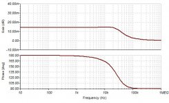
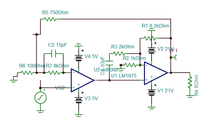
Lm1875 The very special Transfer function
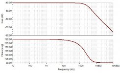
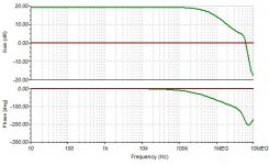
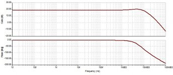
I was amazed by seeing that the LM1875 with gain of 9.2 can still receive extra NFB without oscillating and reach 5Mhz. I looked upon the transfer function with jaw fallen. Have a look.
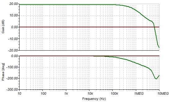
Did you see it, incredible, I could get first order transfer function only with open loop, feedbackless amplifiers. The cut frequency is 700khz but instead of cutting with -90°shift it is -45° and goes all the way to 5Mhz. This why on contrary to other composites where the amp is at its max phase margin, the opamp than needs to be much slower to carry the dominant pole. Here it is the amp is carrying the dominant pole, and opamp should be the fastest possible to let the amp louse alone its phase margin at 5Mhz. Now, that I understand the very particular character of this Lady, I will treat her with still more perseveringly.
I was amazed by seeing that the LM1875 with gain of 9.2 can still receive extra NFB without oscillating and reach 5Mhz. I looked upon the transfer function with jaw fallen. Have a look.
Did you see it, incredible, I could get first order transfer function only with open loop, feedbackless amplifiers. The cut frequency is 700khz but instead of cutting with -90°shift it is -45° and goes all the way to 5Mhz. This why on contrary to other composites where the amp is at its max phase margin, the opamp than needs to be much slower to carry the dominant pole. Here it is the amp is carrying the dominant pole, and opamp should be the fastest possible to let the amp louse alone its phase margin at 5Mhz. Now, that I understand the very particular character of this Lady, I will treat her with still more perseveringly.
Attachments
The mysterious LM1875
Do you remember on post 33 I tested FF's version using inverter mode? It had a strange behavior at the transient, the negative input for short period behaving as positive input.
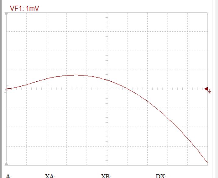
Well, I wanted to take advantage of this defect and apply both inputs at short period, here is the miracle,
Now, the dominant pole of 700khz is extended to above 100Mhzzzz!?#@%$&¶~€.
Do you remember on post 33 I tested FF's version using inverter mode? It had a strange behavior at the transient, the negative input for short period behaving as positive input.
Well, I wanted to take advantage of this defect and apply both inputs at short period, here is the miracle,
Now, the dominant pole of 700khz is extended to above 100Mhzzzz!?#@%$&¶~€.
Attachments
Last edited:
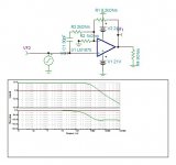
With a parallel feed involving a power amplifier block and a high speed op.amp feeding into a common load ask yourself what of levels of current are passed by each of these and what individual voltages will in the nfb signal if the power amplifier block is able to deliver 4 A and the high speed op.amp around 100 m.a. or less.
This gives with very wide band amplifier driving the power. I don't say any more opamp. The frequency response is over 10Mhz and what an ultra fast transient!
The distortion should be slightly higher but I am in great certainty, this is ultra high definition amplifier.
It is not easy to understand if you don't know how CFA works. In short, the impedance of the negative input determines the open loop gain.
This is the input amplifier's transfer function.

The scope graph transient is 20ns scale. I have never seen such.

The distortion should be slightly higher but I am in great certainty, this is ultra high definition amplifier.
It is not easy to understand if you don't know how CFA works. In short, the impedance of the negative input determines the open loop gain.
This is the input amplifier's transfer function.
The scope graph transient is 20ns scale. I have never seen such.
Attachments
Last edited:
- Status
- This old topic is closed. If you want to reopen this topic, contact a moderator using the "Report Post" button.
- Home
- Amplifiers
- Chip Amps
- The LM1875 for best