Message 86 your 2-diode limiter will not work .The one I suggested will work without distortion.
It is not difficult to check.Even in the Tina simulator
It is not difficult to check.Even in the Tina simulator
Last edited:

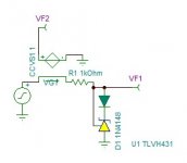
Thank you Maxim to have reactivate the subject. I got an idea of using 1.2v reference TLV431. It has very sharp cutoff but diode 0.6v in reverse. I put inside the loop a diode, uttered the magic word hocus-pocus and it worked.

Attachments
Last edited:
The circuit has 2k impedance when not clipping. If I adapt the series resistor, it can work with soft clipping.Something like this


Adopted, thanks.
Last edited:
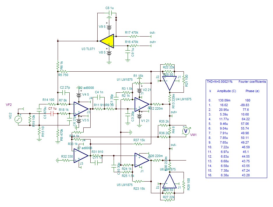
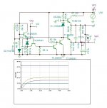
The Finish line is on view. As I stated on early post, the inverter will inject even order harmonics to the bridge. The THD+N measures 0.00021% but mainly even harmonics.
Attachments
Last edited:
I changed the feedback path to take it from the output with correction to perfect it. This is the response with input R=0.

I added a potentiometer to the parafeed to adjust the balance of the bridge gain. This can increase or decrease the even order harmonics bringing the distortion down to 0.00015%.
Attachments
Distortion can't get much lower than that. I like your work kokorianz! Hopefully someday I have skills and time to build one 🙂
Thank you for encouragement. It is possible to reduce much further the distortion with error corrector as post 56, I don't think in listening, putting the corrector on/off will give any difference. So will avoid such gadget. This amp can already be qualified not only ultra high definition, also "world class high precision".
Last edited:
My pleasure! I remember you had an amplifier project some time ago that had inverse polarity 3rd harmonic, which is an interesting idea, whats next now that you have explored the realms of distortion so well? Enjoying the ride at spectator seat and I envision more interesting projects ahead, thanks for providing! 🙂
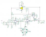
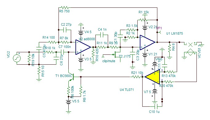
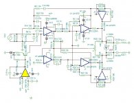
The biasing the +input by 470k resistor, I found it absurd. It doesn't provide any potential, just a current. Why not give a true current source and regulated by itself. The input impedance of AD8008 is 4M, so 100nF is sufficient. This is what shown.

This current bias now on start up will adjust itself approximately while the outputs are muted. Yes, I said muted because the clipper will not be by diodes but with Jfets one each branch, and they unmute gradually to let the approximately adjusted bias pass to the servo slowly and start up without plop.
Now back to clipper and low PSU.
Attachments
Member
Joined 2006
Same here as tmuikku , and, could you tell us which design of yours is your favorite on sound performance? 🙂
NEW class A :Constant Current Push Pull amplifier with single SMPS and hybrid preamp
This amplifier transformed my reference SET300b into decorative object. Despite lot of modification to switched 2A3C, I could bring it close to but remained inferior.
You don't need the preamp if you have low impedance source.
This amplifier transformed my reference SET300b into decorative object. Despite lot of modification to switched 2A3C, I could bring it close to but remained inferior.
You don't need the preamp if you have low impedance source.
Last edited:
The mute jfet does short the input of the LM1875 but due to its on resistance it passes very little voltage which is sufficient to make the servo function. So I use now the servo to bias the input and it works perfect muted as unmuted.
"Vive le progrès"
"Vive le progrès"
Attachments
Member
Joined 2006
NEW class A :Constant Current Push Pull amplifier with single SMPS and hybrid preamp
This amplifier transformed my reference SET300b into decorative object. Despite lot of modification to switched 2A3C, I could bring it close to but remained inferior.
Great, thanks for the reply... noticed I gave a like in that thread too... 😀
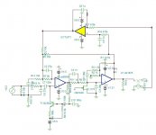
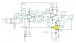
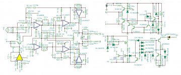
This is the last split supply. The simulator is too slow with single supply.
I will start the PCB. I am an absolute beginner in this matter, so I'll be less present to learn using KiCad.
Attachments
Last edited:
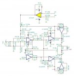
These are the two circuits to create a PCB for each. Toooo simple task for a beginner.
Attachments

Last edited:
I am looking how the arrangement of the PCB layout. The pair of outputs should be very near to each other and the two branches also to have least inductive components. I came up with this topology.

The PCB is flat upon the heatsink, the LM1875s are horizontal mounted in pair on either side, but the feet inserted from bellow. Everything running on +/-5V is on a separate board plugged in, probably all in SMD. At the foot of the module is the +/-5V,V/2 regulator followed by clip/mute.
The 42V regulator and speaker protector is installed also flat with TO3P on heatsink supplying very close distance the two LM pairs.
The LM1875 has flat mounted but not bellow inserted feet, so the diy will ply the feet.
What do you think?
Last edited:
The feedback capacitor.
I am looking about the 330uF feedback shunt capacitor. On site https://linearaudio.nl/sites/linear...0 to 100uF caps and 100 Hz measurements_0.pdf gives distortion measurements of electrolytic 100uf.
It shows how the distortion increases by working potential. I found also that electrolytics increase their capacitance by voltage

Either I add half of the value capacitor to +42V so that increase of one compensates by decrease of the other in push pull, with supply noise problem to resolve, or I add in parallel a capacitor which inversely decreases by voltage as the multi layer ceramic capacitor.

I am looking about the 330uF feedback shunt capacitor. On site https://linearaudio.nl/sites/linear...0 to 100uF caps and 100 Hz measurements_0.pdf gives distortion measurements of electrolytic 100uf.
It shows how the distortion increases by working potential. I found also that electrolytics increase their capacitance by voltage
Either I add half of the value capacitor to +42V so that increase of one compensates by decrease of the other in push pull, with supply noise problem to resolve, or I add in parallel a capacitor which inversely decreases by voltage as the multi layer ceramic capacitor.
It would be useful to replace C5 with a low-esr electrolytic capacitor with double the value.
Capacitors have internal resistance which is non-linear. In any useful value of ceramic capacitor that will far worse than an electrolytic capacitor - definitely a move to avoid.
The dc level in this area is low probably about a diode drop with +/- a.c. small signals being seen by C5.
If you have to bypass C5 go for a stable dielectric like polypropylene.
- Home
- Amplifiers
- Chip Amps
- The LM1875 for best