I have a dead, no sound, Onkyo TX-NR509 surround sound receiver. It died with only 20 hours of use after 8 years, Onkyo says the program and warranty are up on these and issued a 40% coupon on a new unit.
I don't care to buy another, but can't see just trashing this thing since the issue is in the HDMI board not the amp. Apparently the HDMI board and DTS chip controls this whole receiver. The amp is presumably ok but unable to turn on without the functioning HDMI board.
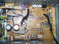
The whole thing is a series of small boards interconnected with ribbon cables. I can clearly ID the HDMI board, the Video board, and the TV board. and the front panel is only connected to the HDMI board.
With those removed, I have what looks like a basic chip amp board with a power supply and transformer off to one side. Most boards are marked 15v + and - .
Since the main amp has only a pair of Sanyo STK 443 chips on it, I would think that the amp board should be able to be powered up and used as a stand alone power amp? The inputs and outputs are attached, the transformer appears to be wired into the protection relay section. I'm thinking that it may only be a matter of either supplying power to a particular section or making a certain connection to power up just the amp itself. The main amp board had no connection to the front panel, that all connected to the HDMI board and video board.
Has anyone else tried this on a newer amp? My thought is that it is an 80wpc amp in two channel, and if I were able to power it up as a stand alone main amp, it may make a decent garage system rather than just sending it to the dump or stripping it for parts.
I don't care to buy another, but can't see just trashing this thing since the issue is in the HDMI board not the amp. Apparently the HDMI board and DTS chip controls this whole receiver. The amp is presumably ok but unable to turn on without the functioning HDMI board.
The whole thing is a series of small boards interconnected with ribbon cables. I can clearly ID the HDMI board, the Video board, and the TV board. and the front panel is only connected to the HDMI board.
With those removed, I have what looks like a basic chip amp board with a power supply and transformer off to one side. Most boards are marked 15v + and - .
Since the main amp has only a pair of Sanyo STK 443 chips on it, I would think that the amp board should be able to be powered up and used as a stand alone power amp? The inputs and outputs are attached, the transformer appears to be wired into the protection relay section. I'm thinking that it may only be a matter of either supplying power to a particular section or making a certain connection to power up just the amp itself. The main amp board had no connection to the front panel, that all connected to the HDMI board and video board.
Has anyone else tried this on a newer amp? My thought is that it is an 80wpc amp in two channel, and if I were able to power it up as a stand alone main amp, it may make a decent garage system rather than just sending it to the dump or stripping it for parts.
Onkyo TX-NR509 Audio Video Receiver Manual | HiFi Engine
Jumper POWERD to GNDDG. Does relay RL901 clack and power come up?
> connection to power up just the amp itself.
I don't see much problem powering up "everything", even the junk HDMI board.
Jumper POWERD to GNDDG. Does relay RL901 clack and power come up?
> connection to power up just the amp itself.
I don't see much problem powering up "everything", even the junk HDMI board.
Attachments
I have read that the cause of no-sound on Onkyo AV amps is dry joints on the DSP chip. Allegedly runs hot, and sits above other hot running parts. Can be fixed by reflowing/removing and resolding the DSP chip, if you are digging into the amp and have a hot air gun might be worth playing with before you strip it down.
I just read that it is a battery in the case of the TX-SV919THX, that’s on the display board. It goes dead after years and gives the effect of no signal passing to the amplifier.
I just got a very quiet one of those for free and decided to bypass all the processors and ICs to allow the rca jacks to go directly to the amp inputs. I plan to give it to someone for a garage amp. I didn’t think it was in the cards to repair something that I didn’t care much about anyways.
I just got a very quiet one of those for free and decided to bypass all the processors and ICs to allow the rca jacks to go directly to the amp inputs. I plan to give it to someone for a garage amp. I didn’t think it was in the cards to repair something that I didn’t care much about anyways.
I tried reflowing the chip but it didn't get it going. Onkyo gave a gift certificate for 40% off a new receiver but I wasn't interested. My bets are on a bad chip in this one, if I press on the chip, the receiver turns off, the chip doesn't even get warm. The other chip on the board is all blackened around the edges too, so my guess is it just got to hot. I also won't go into service mode.
I have zero use for a surround receiver, but a spare garage amp would be fine.
As it sits, nothing but the display powers up, the HDMI board is what turns on the amp from what I'm told. I need to figure out how to turn on the amp as a stand alone, no control panel, no hdmi board, no video board. Just the power supply and amp.
I'm not sure how the HDMI board powered up the amp, which set of leads? Is it a matter of jumping two wires or feeding power into the main board? It looks to me like two of the wires from the transformer go right to the amp board directly, so my guess is its got power there somewhere, but its waiting to be switched on somehow.
When I jump POWERD to GNDDG only the relay on the power board clicks, nothing else seems to come on. The other relays remain silent.Onkyo TX-NR509 Audio Video Receiver Manual | HiFi Engine
Jumper POWERD to GNDDG. Does relay RL901 clack and power come up?
> connection to power up just the amp itself.
I don't see much problem powering up "everything", even the junk HDMI board.
That relay comes on and stays on normally even with the bad HDMI board, but the two relays closest to the speaker outputs click back off after a few seconds.
With the HDMI board connected, the unit won't stay powered up, it comes on for a few minutes then clicks back off again randomly.
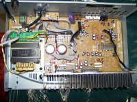
The main amp board has two black cables that go to the HDMI board, one 7 pin, one 5 pin.
The power board has no connection to the amp board, the 5 pin cable to the relay goes to the HDMI board as well. I don't think anything on the HDMI board is working. All I get is the display lights and the ability to select functions, but nothing is actually being switched. The amp board never gets powered up but the main relay and protection relays do click with the board in place, but the left output relay clicks back off almost instantly. Fully assembled, I never see any power to the STK modules.
I think the best bet is to try and power it up minus the HDMI board and Video board.
Without the HDMI board, the display panel will also be dead, so that too has to go as well. I don't see anyway for the control panel to remain active in anyway, and with what I'd like to do, I don't need it anyway.
All that needs to happen is for the amp to power up and process sound.
The 5 wire black ribbon to the power board is an output of the HDMI board, what do the other boards do? The gray ribbon cables are speaker outputs to the terminals. Without the HDMI board, there's no power connection to the main amp.
Attachments
If everything is dead, and no control is working, then you likely won't have any volume control and anyway to get audio through the existing audio circuits.
If you want to use the amp sections, remove everything you can, and get the power to the amps working. The relay on the power board will power up the main transformer when wired to be on. Or remove the relay and put some solid wire links in it's place.
There are also output relays on the amps, so they will probably need bypassing in the same way.
Then find where the audio signals are input to the amplifiers, and break the connection. Connect them to some phono sockets on the back.
Last edited:
The other relays are likely protection relays, I don't see any reason to defeat those?
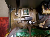
Right now, there's no power to the main amp board, the power supply board transmitted its power through the HDMI board which is dead. With the HDMI board in place, only the right channel stayed powered up, it would power up the amp, then shut it right back down again in a few seconds, then if left on, the display would flash a few times and the whole thing would go down. One of the chips on the HDMI board, the larger one, would get super hot really fast, the EDS chip didn't even get warm. That board is bad, and leaving it in place would draw excess current for no reason, if not damaged the power supply.
I can turn on the power supply but I need to figure out how to power the amp board up, its likely going to be through one of the two black cables that remain, either the 7 wire or the 5 wire flat cable. I'm guessing its going to be a matter of connecting pins 2, 3, and 4 to the right leads on one of the black cables on the amp board to power it up.
The amp board has two STK chips, the larger one is for the main two channels, the other looks to power up the rear and center speakers. I don't care about those, but I'm not sure I can power up just the one chip.
I need to know which of the flat black cables is going to be the one to power up the amp itself.
It won't have a volume control, that'll be up to which ever pre-amp I connect to this.
Another "Made In Maylasia" receiver tosted.
When I browsed Best Buy and Circuit City's audio isle, I turned around each home theater receiver and just shook my head - "Made in" asia labeled garbage and expensive pricing.
Shame this is what happened to the major brand names - outsouced junk.
And in the shop I had loads of customers bringing in that crap, I felt sorry for them.
How were they to know that they were buying something failure-prone?
Most of the time I didn't repair their stuff - couldn't get parts!
The landfills are overflowing with that stuff.
I'm glad I stuck with my "boring" and still fantastic 2 channel Technics from 1989, before outsourcing and greed kicked in.
In my professional opinion, the system of HDMI is the worst thing to be born.
Reasons being, it's fragile - the connectors, cables, and electronics involved (as pitbul mentioned)
Sure, there are individuals that will stand by their opinion of "it's great, only one connector to deal with".
Well, you go ahead and praise that crap.
Because we never had so many product failures before that nasty connector was born.
The "old school" RCA connectors were much more robust and reliable.
It doesn't matter if the HDMI chips are bad or not, no parts are available for this. The only course of action according to Onkyo is to ship it to an Authorized repair center, and if the HDMI board is found at fault, they issue you a 40% off coupon on a new unit. They apparently do not service or repair that board. I also wouldn't put a dime into it at this point. It came with the house I bought, I didn't buy it or choose it.
As it sits now, its a dead unit on a shelf. Its been replaced in my system already but an older unit I already had.
The question isn't whether or not the HDMI board of chips turn on the protection relays. I need to know where or how to power up the main amp board by itself.
Something I'm not seeing is a rectifier in the power supply, the only rectifier I see is on the middle board, or the board that contains the video in/out jacks. (U0021 on the diagram).
What I'm basically trying to figure out is if the main amp board can be powered up by itself, sans all the other crap.
It appears that the power supply isn't capable of supplying the correct or enough power for the amp board if the rectifier is mid circuit on the video board and not on the power supply. The transformer supplies at least 5 AC voltages.
What I find odd is that the power supply board stands alone, then the rectifier is on one board, and the filter caps are on the main amp board rather than with the power supply. It looks to me like all the amp circuit is on the main amp board but there's no single source for power distribution.
Maybe the right answer is to reconfigure the power supply to just power the main amp board and toss everything else. That would mean taking the rectifier and 10k cap from the U0021 and moving it to the power supply to make a feed to power up the main amp section.
The speaker 'relays' are the protection relays, they generally turn off the speakers if DC volts are detected at the outputs.
Or
Maybe the best thing to do is strip this thing for its usable parts and toss it?
Last edited:
....how to power up the main amp board by itself. Something I'm not seeing is a rectifier in the power supply, the only rectifier I see is .....the board that contains the video in/out jacks. (U0021 on the diagram).
It's there in the service notes. 107 pages,
 13 pages of schematics
  . I don't know why I looked; I don't have a NR509.
Attachments
I can't say for that model but I had HDMI go bad in an Onkyo TX-SR707 and it was quite a job to get it going. I got another year out of reflow and a little more out of a used HDMI board. But then I just could not get it going again.
To salvage the amplifier section I ended up using an Arduino Nano to sequence all the relays, check the I_PROT and V_PROT signals, etc.
I think the program sequence was basically:
0. Rewire the power supply for the relays and Arduino.
1. Engage Main Power Transformer Relay
2. Check V_PROT & I_PROT & Delay [Shut Off All Relays If Any Fault.]
3. Enable H_SEC (High Voltage Secondary Relay - I don't think your STK model has that)
4. Check V_PROT & I_PROT & Delay [Shut Off All Relays If Any Fault.]
5. Enable Speaker Relays
6. Enter Endless Loop: V_PROT & I_PROT. [Shut Off All Relays If Any Fault.]
I basically had to take over those functions from the built-in micro.
You can figure it out from the service manual. Unfortunately your STK based model will be a fair bit different from my TX-SR707 model.
You might find a simpler solution but I did what I did so that the protection circuits would still function.
I used A0, A1 and A2 on the Arduino Nano (Analog/ADC inputs) to read the V_PROT, I_PROT and the high power (don't recall the name) signal.
Last edited:
- Status
- This old topic is closed. If you want to reopen this topic, contact a moderator using the "Report Post" button.
- Home
- Amplifiers
- Chip Amps
- Salvaging amp from dead Onkyo?