My Technics SU-V4K has been giving me a bit of grief the last couple of years.
I've had the unit since new, summer of 1981 (!) and it has never been serviced, so it is still un-adulterated, except for my contact spray cleaning.
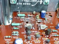
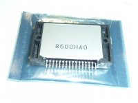
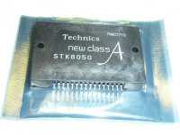
I also bought a set of the STK8050 's out of GB a few years back, just in case. Hope that those are originals as stated, and not the knockoffs
I've cleaned the pots a few times in the last 10 or so years. It started with the volume dropping off to almost nothing on one of the two channels (not always the same one). The volume appeared to be higher on the right side, so the balance was been staying just a bit off-center to compensate. I’d been turning the volume up-down while the unit is turned off. I had found that the 'dropped' channel side comes back when I gave the poor amp "a sharp slap between the ears" - i.e.- hit the cabinet simultaneously left/right on the sides with a slapping motion. Things get back to normal real quick. LOL.
So, over on the AK forum, SVI2004A suggested looking for loose / cold solder joints etc. and checking the relay contacts.
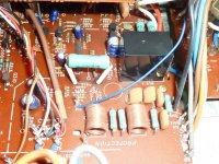
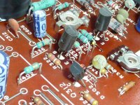
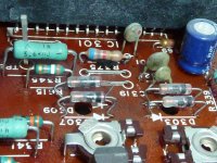
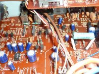
I've looked over the PCB from both sides, I found one solder pad connecting R375 to TH301 had lifted from the PCB, along with the components. I resoldered these two together, so I don't believe there is an issue here anymore. Guess that's why it's black under the resistor. I would say this is on the Left Channel.
I used DeOxit on the switches / pots (sprayed it in through the little openings).
Unfortunately, the other day the right channel dropped off and I no longer get any sound out of it. The LCD meter shows no activity on that channel.
Doesn't matter which input (AUX / Tape / Tuner) I use, there's no sound from the right.
So... I've opened it again.
The two little fuses next to the relay are good. The amp still makes the 'click' shortly after I turn it on.
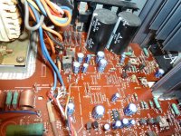
I took pics of the main & side boards a year ago and again today. I'm not seeing anything different. Small dark spots under a couple of transistors ( Q314 & Q316 ) and under R375, but I don't believe it's anything major. I think the spot under the resistor is from heat during the original installation, as that one is physically larger than the one at R376 and the solder joint doesn't look as nice as the others.
I was able to open the relay, saw a bit of corrosion (darker spots) and cleaned both of the contacts. It appears to operate just fine.
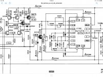
I was then able to do some "Troubleshooting" as per the SU-V4a Service Manual, using my Fluke27. Hope I'm measuring it correctly (DC mV).
Clamp Voltage L channel TP301-TP303 (negative probe) was 0.7, was able to adjust it down to 0.5 as per the procedure. ICQ L channel then adjusted to the correct clamping voltage of 15.5. Both readings were relatively stable.
When checking the Right channel, there is no post on TP304, just a pad. Hope this is correct. Clamping voltage is all over the place, both negative and positive mV, doesn't matter where R338 is located. As such, there was no point in trying to adjust the ICQ, as it also all over the place.
Guess I have a bigger problem somewhere....
Can't figure out what the other TP 's are for as the "Manual" doesn't really go into these.
I've had the unit since new, summer of 1981 (!) and it has never been serviced, so it is still un-adulterated, except for my contact spray cleaning.
I also bought a set of the STK8050 's out of GB a few years back, just in case. Hope that those are originals as stated, and not the knockoffs
I've cleaned the pots a few times in the last 10 or so years. It started with the volume dropping off to almost nothing on one of the two channels (not always the same one). The volume appeared to be higher on the right side, so the balance was been staying just a bit off-center to compensate. I’d been turning the volume up-down while the unit is turned off. I had found that the 'dropped' channel side comes back when I gave the poor amp "a sharp slap between the ears" - i.e.- hit the cabinet simultaneously left/right on the sides with a slapping motion. Things get back to normal real quick. LOL.
So, over on the AK forum, SVI2004A suggested looking for loose / cold solder joints etc. and checking the relay contacts.
I've looked over the PCB from both sides, I found one solder pad connecting R375 to TH301 had lifted from the PCB, along with the components. I resoldered these two together, so I don't believe there is an issue here anymore. Guess that's why it's black under the resistor. I would say this is on the Left Channel.
I used DeOxit on the switches / pots (sprayed it in through the little openings).
Unfortunately, the other day the right channel dropped off and I no longer get any sound out of it. The LCD meter shows no activity on that channel.
Doesn't matter which input (AUX / Tape / Tuner) I use, there's no sound from the right.
So... I've opened it again.
The two little fuses next to the relay are good. The amp still makes the 'click' shortly after I turn it on.
I took pics of the main & side boards a year ago and again today. I'm not seeing anything different. Small dark spots under a couple of transistors ( Q314 & Q316 ) and under R375, but I don't believe it's anything major. I think the spot under the resistor is from heat during the original installation, as that one is physically larger than the one at R376 and the solder joint doesn't look as nice as the others.
I was able to open the relay, saw a bit of corrosion (darker spots) and cleaned both of the contacts. It appears to operate just fine.
I was then able to do some "Troubleshooting" as per the SU-V4a Service Manual, using my Fluke27. Hope I'm measuring it correctly (DC mV).
Clamp Voltage L channel TP301-TP303 (negative probe) was 0.7, was able to adjust it down to 0.5 as per the procedure. ICQ L channel then adjusted to the correct clamping voltage of 15.5. Both readings were relatively stable.
When checking the Right channel, there is no post on TP304, just a pad. Hope this is correct. Clamping voltage is all over the place, both negative and positive mV, doesn't matter where R338 is located. As such, there was no point in trying to adjust the ICQ, as it also all over the place.
Guess I have a bigger problem somewhere....
Can't figure out what the other TP 's are for as the "Manual" doesn't really go into these.
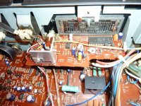
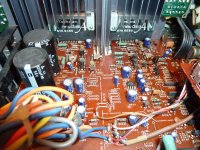
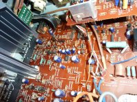
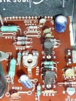
Here are some pics of my PCB:
Attachments
-
 P1200898m.jpg297.9 KB · Views: 77
 -
 P1200897m.jpg342.9 KB · Views: 87
 -
 P1200896m.jpg352 KB · Views: 241
 -
 P1200895m.jpg362.1 KB · Views: 68
 -
 P1200894m.jpg367.2 KB · Views: 75
 -
 P1200893m.jpg269.4 KB · Views: 76
 -
 P1200890m.jpg278.3 KB · Views: 132
 -
 P1200889m.jpg274.3 KB · Views: 141
 -
 P1200888m.jpg388.6 KB · Views: 137
 -
 P1200887m.jpg451 KB · Views: 140
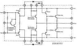
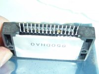
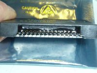
I also have a couple of pics of my "Replacement" STK-8050's.
I do see some difference to the units in my AMP -
1. The Typeface is slightly different note the "T" etc.
2. the "A" logo is a bit different as well
3. On the ones that are installed in my amp, the first and last two contact legs are bent backwards, on the replacements, they are all in the same direction.
4. The installed ones have a small white dot below the "STK"
Wondering if these are counterfeit or a different series? I know the installed ones are the originals.
Attachments
OK, did a bit of "Research" and figure that I measure between chassis ground and whatever. So here it goes:
When the unit is switched on from cold, the FL meter on the face went to a 30 on the low range, then the level slowly dropped down to the 0.1 in around 1 minute. Nothing is connected to the amp, volume turned down and all other pots centered, switches to 'off'
I measured both STK's from below, the soldered side of the PCB.
Left channel (good) both pins 10 & 11 read O.L.
Right channel (no sound), pin 10 goes from -65 to +56 mV dc.
Pin 11 reads O.L.
So, I guess that the wildly fluctuating mV are no good and that that power amp / driver is no good...
Looks like R375 was replaced (most likely knocked off when old ic failed) (you say left channel is working now)
With that set ODD # is left ch - even # is right ch
Examples R375 R376 TH301 TH302
It’s helpful for comparing things (voltages at locations) to other channel
R376 is it 6.8K and what resistance is TH302? (Removed from board)
Are the OA90 diodes all ok?
With that set ODD # is left ch - even # is right ch
Examples R375 R376 TH301 TH302
It’s helpful for comparing things (voltages at locations) to other channel
R376 is it 6.8K and what resistance is TH302? (Removed from board)
Are the OA90 diodes all ok?
Thanks a bunch Bailey.
This amp has never been serviced previously. I bought it new and haven't done anything to it aside from contact cleaner... yet. It was a Military Market unit with the multi Voltage adjustments.
So both STK's have been in it all of the time. I picked up 3 replacement STK-8050's out of GB a few years back (just in case they are ever needed), with the assurance that they are 'Originals' from a Panasonic Service center. Hope that it's the case.
But yea, R375 is slightly larger than its' mate on the other side. And the pad on the bottom where it joins up to the thermister is loose from the board, but these are the only components on that trace, so I think it should be fine.
Left channel is working.
Do I remove the diodes to check them as well? I guess I can check the transistors while still on the board, or do I have to lift one leg? (Can't you tell, I'm so knowledgeable on this stuff... that it's dangerous...)")
Will see what I can find tomorrow...its' way past my bedtime here.
This amp has never been serviced previously. I bought it new and haven't done anything to it aside from contact cleaner... yet. It was a Military Market unit with the multi Voltage adjustments.
So both STK's have been in it all of the time. I picked up 3 replacement STK-8050's out of GB a few years back (just in case they are ever needed), with the assurance that they are 'Originals' from a Panasonic Service center. Hope that it's the case.
But yea, R375 is slightly larger than its' mate on the other side. And the pad on the bottom where it joins up to the thermister is loose from the board, but these are the only components on that trace, so I think it should be fine.
Left channel is working.
Do I remove the diodes to check them as well? I guess I can check the transistors while still on the board, or do I have to lift one leg? (Can't you tell, I'm so knowledgeable on this stuff... that it's dangerous...)
Will see what I can find tomorrow...its' way past my bedtime here.
1st call with set off check Rch STK (IC302) check with power off continuity from pin 2-3 and pin 3-4 (should be 0.2-0.3 ohm) - this ensures Emitter resistors are ok (definately check if thermistor TH302 or R376 was open)
Of that checks out, power set up
Checklist for 2V at collectors of Q314 and 316 (drive from differential amp)
If 2V isn’t there at both points, other voltages on STK won’t add up
If ok... check voltages on Rch STK - it may help find what is adrift.
As for OA90 diodes can check with one pin lifted. (These are germanium diodes) - with power off
The fact that it used to work after a whack, is screaming dry joint..... now to find it.
Last edited:
What you could do is a mp3 of the signal - simply just play it back from pc or iPod etc
Use your meter - jheck on AC mv or ACv
As volume increases you’ll see a reading on your meter.... of 0mvAC there’s no signal making it to power amp stage - then look at tone board/ volume board & input selectors
All is good... just we gotta spend time finding how far the signal is going
Use your meter - jheck on AC mv or ACv
As volume increases you’ll see a reading on your meter.... of 0mvAC there’s no signal making it to power amp stage - then look at tone board/ volume board & input selectors
All is good... just we gotta spend time finding how far the signal is going
OK, was able to do some checking on it tonight.
1. Continuity checks - IC302 --> 2-3 0,3ohm, 3-4 0,3. IC301 --> 2-3 0,3, 3-4 0,3
2. Voltages to Gnd: Q314 --> E= 51.0Vac, C=1.962, B= 50.1
Q316 --> E= -51.0, C= -1.894, B= -50.3
Q313 --> E= 50,8, C= 2.117, B=50.4
Q315 --> E= -51.0, C= -2.092, B= -50.4
3. So, as suggested, I went to measure the individual pins of the STK's. Measure from the bottom (solder side) as there is better access.
Alas, I think I royally f*d up. Slipped with the probe from pin 1 onto 2 and there was a spark and a bit of smoke. Not pretty. So, shut off power to the set to prevent further damage.
4. Went to remeasure the continuity on 302: 2-3 is now O.L., 3-4 is still 0.3 . Don't think that's good...
My thoughts: IC302 was (!) probably good. Not so anymore...
The voltages on the Transistors were in the ball park, could be adjusted somewhat but the +/- 50V were a little higher than they should be by around 5Vac, if I'm reading the schematic correctly.
Did find some test tones on the net and saved them. How do you feed them into the amp?
Have not measured the resistor nor the thermister yet, as I think it's now a little worse than when I started.
Last edited:
Lesson ONE learned: never let the test probe slip from it's intended position, nor let it come into contact with anything else on the way to and/or from the intended position.
So, I'll begin unsoldering the old STK. Is there anything of value on/in the black box? Otherwise, I think I would just cut the legs off and then take it out. If I were to unsolder- use a solder sucker or braid?
Do you think the STK's I have are originals or fakes?
So, I'll begin unsoldering the old STK. Is there anything of value on/in the black box? Otherwise, I think I would just cut the legs off and then take it out. If I were to unsolder- use a solder sucker or braid?
Do you think the STK's I have are originals or fakes?
Last edited:
I use braid - I got to the point where I never have stretched or bent pins and pcb suffers no stress from removal.
The STKs should be fine... there was a re run done that was not counterfeit- I have installed a few over the years... it’s been 4 years since I’ve worked on a V4
The STKs should be fine... there was a re run done that was not counterfeit- I have installed a few over the years... it’s been 4 years since I’ve worked on a V4
OK, I haven't been idle. Needed to pick up some stuff.
Went out and bought a (hopefully) proper iron - got myself a Hakko FX-888D. Hope that it's OK, but it was the only one that my local electronics store had that was still (somewhat) within my budget. Then picked up some braid as you suggested, as well as thermal paste. Will have to deal with the other required things as the list grows.
First thought- the new iron beats my ancient Ungar 45W hands down. I really like it and is making the job much easier. Some goes with the braid. Especially when removing the diodes that are partially blocked by the heat sink support bracketry. Thanks for your suggestions/pointers . Much appreciated. 
I have removed IC302 (the STK8050) by removing the upper heatsink, unscrewing the IC302 (nice that they made some holes in the side board to allow access to the attachment screws).
So, here are some numbers:
D304 & D307 beep on the tester and give me 0.235
D308 beeps and shows at 0.233.
D310 does not beep and is O.L, which makes me SOL. BTW - the diodes are stamped 08 or 80, whichever way one reads them.
TH302 and R376 are both O.L. as well .
So, what do I remove / check next? I've removed the US components from the board for now, so I don't get too confused here...
Went out and bought a (hopefully) proper iron - got myself a Hakko FX-888D. Hope that it's OK, but it was the only one that my local electronics store had that was still (somewhat) within my budget. Then picked up some braid as you suggested, as well as thermal paste. Will have to deal with the other required things as the list grows.
First thought- the new iron beats my ancient Ungar 45W hands down. I really like it and is making the job much easier. Some goes with the braid. Especially when removing the diodes that are partially blocked by the heat sink support bracketry. Thanks for your suggestions/pointers
. Much appreciated. I have removed IC302 (the STK8050) by removing the upper heatsink, unscrewing the IC302 (nice that they made some holes in the side board to allow access to the attachment screws).
So, here are some numbers:
D304 & D307 beep on the tester and give me 0.235
D308 beeps and shows at 0.233.
D310 does not beep and is O.L, which makes me SOL.
BTW - the diodes are stamped 08 or 80, whichever way one reads them.TH302 and R376 are both O.L. as well .
So, what do I remove / check next? I've removed the US components from the board for now, so I don't get too confused here...
Last edited:
- Status
- This old topic is closed. If you want to reopen this topic, contact a moderator using the "Report Post" button.
- Home
- Amplifiers
- Chip Amps
- Technics SU-V4K (E) One channel dead