I have just swaped JRC4558D for KA4558.
Am I tripping or KA is better. I think that the sound is more sharp and that the bass sounds better.
Just a different manufacturer. JRC is Japanese Radio Corporation, KA could be any one of a number of different brands.
Try the TL072, that's one of my favourites.
You need a more powerful PSU.
60W torodial transformer.
Diodes with fast recovery.
4700 uF caps.
15 V DC regulator.
470 uF at the output of voltage regulator.
For your design or for what I have now? Its not clipping or anything.
Just a different manufacturer. JRC is Japanese Radio Corporation, KA could be any one of a number of different brands.
Try the TL072, that's one of my favourites.
Oh, I touhgt that I heard difference.
There is a very real phenomenon (which we all experience) called 'experimenter expectation' where you can think you hear a difference (and in your own mind you are sure), and yet if you listened blind and without knowing which device was fitted first the results would be more random.
You may well hear more of a real difference going to the TL072 or NE5532.
Ultimately you have only yourself to please, and so you should always trust what you hear and not be influenced to much by what you may read about certain devices and so on.
You may well hear more of a real difference going to the TL072 or NE5532.
Ultimately you have only yourself to please, and so you should always trust what you hear and not be influenced to much by what you may read about certain devices and so on.
Here is the schematics:
When you build this, please report the sound...
There is a very real phenomenon (which we all experience) called 'experimenter expectation' where you can think you hear a difference (and in your own mind you are sure), and yet if you listened blind and without knowing which device was fitted first the results would be more random.
You may well hear more of a real difference going to the TL072 or NE5532.
Ultimately you have only yourself to please, and so you should always trust what you hear and not be influenced to much by what you may read about certain devices and so on.
So I bought and tested TL072 and NE5532
First I tested TL072 and then NE5532... well I instantly swapped back to TL072.
Highs on NE5332 reminds me on 4558, they are hissing like a snake, bass is not as tight and there is less dinamics.
But I really like TL072, bass is even tighter than with no preamp connected.
If I will get the same sound on big PA speakers, I will stay with this circuit. I realy like the sound.

That's good
I've always liked the TL072 series of opamps, in fact many years ago they were pretty much the ultimate audio choice.
Used correctly, and within their performance envelope and I still think they take a lot of beating.
Yes, I can see why TL072 was ultimate audio choice, ofcourse now we have better technologies, but hard to DIY because of it`s size, digitaly controlled, etc...
Is it possible to add adjustable 3rd order LPF -low pass filter for the subwoofer to this amplifier that I could also turn off and on?
Yes, I can see why TL072 was ultimate audio choice, ofcourse now we have better technologies, but hard to DIY because of it`s size, digitaly controlled, etc...
Is it possible to add adjustable 3rd order LPF -low pass filter for the subwoofer to this amplifier that I could also turn off and on?
With use of 10k pot for frequency adjustment if possible
So I did some reserach on the internet and found out that I`m better of making another circuit for lpf.With use of 10k pot for frequency adjustment if possible
I found out this design, but I need to make gain of 12dB for my amplifier.
I think that I should change R11 and R12.
This was writen with the scheme "There is an inherent gain of 2 (6dB)"
So that means that gain of 4 = 12dB?
and that I should use 3k3 and 10k resistors -the same as on preamp I builded?
Should I add Cin 0.47uf in series with the input for dc filtering? and Cout 22uF in series with the output and Load 100k resistor to the ground?

Last edited:
R11 and R12 set the gain in the same as in your circuit but remember, this filter is drawn for using a split supply, not single rail. R1 should be much larger than 10k because this value partly sets the input impedance. If you make R1 a 470k then you can use a small 0.47uF input cap. An output cap is always a good idea.
You can not easily make this adjustable because you need to change all three filter resistors together or all three caps.
You can not easily make this adjustable because you need to change all three filter resistors together or all three caps.
for a bass only amp the crossover/filter can use an MFB filter topology.So I did some reserach on the internet and found out that I`m better of making another circuit for lpf.
I found out this design, but I need to make gain of 12dB for my amplifier.
I think that I should change R11 and R12.
This was writen with the scheme "There is an inherent gain of 2 (6dB)"
So that means that gain of 4 = 12dB?
and that I should use 3k3 and 10k resistors -the same as on preamp I builded?
Should I add Cin 0.47uf in series with the input for dc filtering? and Cout 22uF in series with the output and Load 100k resistor to the ground?
View attachment 652727
MFB is inverting and so the input can accept TWO signals and adds them (it is effectively a mixer). Thus you get 2times gain (+6dB) for free and then the single opamp gives you and inverted 2pole filter.
You have the option to add on a second opamp to create a 4pole filter and if you need to invert back to same polarity.
The 2 pole and the 4 pole can be set up for Butterworth, or Linkwitz-Riley, or Bessel. You choose. Most would go LR4 for both the low pass to the bass only and for the high pass to everything else.
http://www.ti.com/lit/an/sboa114/sboa114.pdf
http://www.ti.com/lit/an/sloa049b/sloa049b.pdf
http://www.analog.com/media/en/training-seminars/tutorials/MT-220.pdf
Multiple Feedback Low-pass Filter Design Tool
D.Self warns against using MFB for the high pass filter. Use S&K, either the unity gain version, or the equal component value (ECV) version which uses gain to set the Q independently from the frequency setting components. This is a big advantage for the ECV as used by Ben Duncan and others.
Last edited:
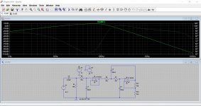
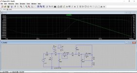
So I builded the crossover from the schematics that I posted earlier.
I`m running it at +-18v.
I added 0.33uF poliester capacitor at the input for dc protection, changed 10n capacitors to 0,1uF, and 6k8 resistors to 15k.
It should be tuned to 150hz cutoff, I can`t confirm it because I don`t have a scope, but it defenetly sounds right. Bass hits much harder than it did when I used crossover on my soundcard.
It`s not adjustable but it does what it should.
Hi diy1995,
The TL072 was good when it first came out, but it doesn't sound very good compared to OPA2134 for example. I would take an NE5532 over a TL072 any day if that helps you make up your mind. Also, the TL072 has very poor output drive and will not properly drive a 600 ohm load on the output. The 4558 types are in the same boat. The NE5532, LM4562 and OPA2134 will all drive 600 ohm loads all day long.
Your buzz is probably coming from your switching power supply. You should be using a linear regulated +/- 12 ~ 16 V supply, so you need a transformer that outputs about 15 vrms x2, or 30 VCT (30 volts AC with a centre tap). This will give you a linear, bipolar supply. I'm assuming you would use a pair of 15 VDC regulator chips, like the 7815 / 7915 (positive and negative regulator ICs) or 317 / 337 adjustable regulators set for about 15 VDC. If you want to stay with a single supply, then you need about 16 VAC output (transformer) followed by the rectifier and filter capacitors, regulator and filter to your circuit.
The OPA2134 is about the best op amp there is that is reasonably priced. It is a J-Fet input just like the TL072. The others, 4558, NE5532 are bipolar input transistors. The best op amp in that line would be the LM4562 / LME49720.
Good luck on this project, Chris
What value did you make R1 ?
R1 10k.
What capacitor should I use?
Or should I change resistor to 470k?
And I didn't used 3k3 and 10k for gain because when I did I got a loud beep, I left 10k and 10k and connected LPF before the preamp.
Last edited:
Hi diy1995,
The TL072 was good when it first came out, but it doesn't sound very good compared to OPA2134 for example. I would take an NE5532 over a TL072 any day if that helps you make up your mind. Also, the TL072 has very poor output drive and will not properly drive a 600 ohm load on the output. The 4558 types are in the same boat. The NE5532, LM4562 and OPA2134 will all drive 600 ohm loads all day long.
Your buzz is probably coming from your switching power supply. You should be using a linear regulated +/- 12 ~ 16 V supply, so you need a transformer that outputs about 15 vrms x2, or 30 VCT (30 volts AC with a centre tap). This will give you a linear, bipolar supply. I'm assuming you would use a pair of 15 VDC regulator chips, like the 7815 / 7915 (positive and negative regulator ICs) or 317 / 337 adjustable regulators set for about 15 VDC. If you want to stay with a single supply, then you need about 16 VAC output (transformer) followed by the rectifier and filter capacitors, regulator and filter to your circuit.
The OPA2134 is about the best op amp there is that is reasonably priced. It is a J-Fet input just like the TL072. The others, 4558, NE5532 are bipolar input transistors. The best op amp in that line would be the LM4562 / LME49720.
Good luck on this project, Chris
Hello, I will buy OPA2134 after the holydays and try it. I don't need to drive 600ohm load. My amp has 10k input impedance.
Yes buzz was present because of a power supply, after I builded standard 12v regulated power supply hum was gone.
R1 10k.
What capacitor should I use?
Or should I change resistor to 470k?
And I didn't used 3k3 and 10k for gain because when I did I got a loud beep, I left 10k and 10k and connected LPF before the preamp.
What would happen if I use 400k or 500k instead of 470k? I don`t have 470k right now.
- Status
- This old topic is closed. If you want to reopen this topic, contact a moderator using the "Report Post" button.
- Home
- Amplifiers
- Chip Amps
- Making preamplifier...