His R3 = 2M2 is copied from B.Putzeys and I have seen similar in other differential designs.
Yes. I thought it is needed, since B. Putzeys says this resistor will
greatly reduce the current flowing through the signal
wires, and increases CMRR.
Do Rf2 and Cf depend on RF value?No. You still need Cc = 180 pF; Rf2 = 20 kΩ; Cf = 47 pF.
So Rf2 and Cf only needed on feedback resistor like in circuit below?
An externally hosted image should be here but it was not working when we last tested it.
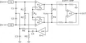
I know this, but Andrew actualy mentioned not those resistors, but said that i need another pair of Rf2 and Cf across R6.Which is question that remains, since it looks like you only sugest them across Feedbanck resistor. Or I am missunderstanding?As Andrew correctly points out, R4-R7 need to be pairwise matched. I.e. R4/R6 = R5/R7 for optimum CMRR
Also: R3 should be 0 Ω.
Doesn't it improve CMRR?
You'll get better performance if you leave the LM3886 with a gain of 20 dB
I reduced gain to 10 and i will use 0.1 % resitors, those square ones. And mount them by pairs touching one another. R4 with R5, R6 with R7.Considering that resistors R6 and R7 have much higher dissipated power than R4, R5 that may be tough to achieve.
And I increased values of them to reduce dissipation.
Do I have good circuit now?
Last edited:
Do Rf2 and Cf depend on RF value?
Yes. Simulate the loop gain of the LM3886 section and you'll see. Also simulate the closed loop small signal transient response as that'll tell you if you have the values tuned in correctly as well.
So Rf2 and Cf only needed on feedback resistor like in circuit below?
As far as I can tell without running a simulation on it, your circuit should be good assuming you size Rf2 and Cf correctly. My only concern is that you'll have a gain of 5 V/V once Rf2 and Cf kick in. That may/may not be an issue. A simulation of the loop gain would answer that question.
Doesn't it improve CMRR?
It does raise the common-mode impedance, which may increase the CMRR. If your source is AC coupled, however, it will also result in a large input voltage offset due to the bias current of the op-amps flowing into the 2M2 resistor.
A more elegant solution would be to bootstrap the CM impedance, but I'm pretty sure THAT Corp has a patent on that, which makes legal reproduction tricky. You can trawl through the patents for the THAT1200 to find out.
Tom
Will do that, thanks.Yes. Simulate the loop gain of the LM3886 section and you'll see. Also simulate the closed loop small signal transient response as that'll tell you if you have the values tuned in correctly as well.
Source will be DC coupled, so I think I wil try it with 2M2 instaled.If your source is AC coupled, however, it will also result in a large input voltage offset due to the bias current of the op-amps flowing into the 2M2 resistor
A more elegant solution would be to bootstrap the CM impedance, but I'm pretty sure THAT Corp has a patent on that, which makes legal reproduction tricky. You can trawl through the patents for the THAT1200 to find out.
EDIT:
Maybe I should just use THAT1200 front end?
And LM3886 inverting / non inverting configuration, of course with all of your sugested parts on LM3886
THAT1200 is not very cheap, but when I calculated cost of my config with 0.1% resistors. I feel dumb now

I thought that I am geting something cheaper, but I was wrong
I can see, that THAT1200 (pun not intended) have extremely good CMRR, and can easily drive any configuration of LM3886.
This circuit looks extremely nice, I don't think I can get even close to its performance:
An externally hosted image should be here but it was not working when we last tested it.
Last edited:
Questions Questions
The input filters using 100r & 470pF have a single pole roll-off (ignoring cable inductance) around 850kHz.
Why is that set so high?
Should that be left unaltered?
Could the RF interfence filter be scaled down to 200kHz?
Would there be any disadvantage to doing that?
The input filters using 100r & 470pF have a single pole roll-off (ignoring cable inductance) around 850kHz.
Why is that set so high?
Should that be left unaltered?
Could the RF interfence filter be scaled down to 200kHz?
Would there be any disadvantage to doing that?
It might be B.Whitlock that holds the patent and that THAT are licensed to manufacture...................
A more elegant solution would be to bootstrap the CM impedance, but I'm pretty sure THAT Corp has a patent on that, which makes legal reproduction tricky. You can trawl through the patents for the THAT1200 to find out.
Tom
https://www.google.co.uk/url?sa=t&r...tAXHaUDZA&sig2=IsPFf97h_ORrPI1NxqOqXg&cad=rja
There is an earlier version of that paper dated 1996 and it omits all references to THAT
The post25 sch is different from the two B.Whitlock papers. Both the B.Whitlock papers show the bootstrapped resistors as well as the bootstrapped capacitors.
Attachments
Last edited:
Note that C1, 2, 3, Pin1 & Shell all go to Chassis.
All others are Power Ground (PG).
And that somwhere PG is connected to Chassis (for safety).
I know, I saw differnt ground symbols.
All the symmetrical signal components still need to be matched.
They would benefit from matching, but this circuit can achieve much better performance even with worse matching, atleast datasheet says so. It has to do with CM pin. Datasheet explains it. And I can use cheap 1% resistors around LM3886. I think 1% everywhere will still give good performance.
The input filters using 100r & 470pF have a single pole roll-off (ignoring cable inductance) around 850kHz.
Why is that set so high?
470pF interactions are described in datasheet. It says that they act like they are in series. It is in page 9.
It might be B.Whitlock that holds the patent and that THAT are licensed to manufacture.
https://www.google.co.uk/url?sa=t&rct=j&q=&esrc=s&source=web&cd=3&ved=0ahUKEwiMi8Db5rDLAhWK5xoKHWF7BB8QFggsMAI&url=http%3A%2F%2Fwww.thatcorp.com%2Fdatashts%2FAES6261_New_Balanced_Input_IC.pdf&usg=AFQjCNG_jnyLkJUP3vgkVI6r-tAXHaUDZA&sig2=IsPFf97h_ORrPI1NxqOqXg&cad=rja
There is an earlier version of that paper dated 1996 and it omits all references to THAT
The post25 sch is different from the two B.Whitlock papers. Both the B.Whitlock papers show the bootstrapped resistors as well as the bootstrapped capacitors.
Circuit from this post (which i don't know how to quote) is in THAT1200 datasheet too.
If you read the B.Whitlock early paper you will see that he refers to a 1ohm error and what that does to the CMMR.
The 100r in the filters look like source impedances to the balanced receiver. You need to match them.
Similarly the capacitors appear as input impedances. These too need to be matched.
The bootstrapping improves the CM impedances of the differential resistances and capacitances. This improves the Receiver tolerance to imbalance in the Receiver as well as improving the bridge's tolerance of imbalance in the Source.
But don't add to Receiver, or Source, imbalances.
The purpose of the InGenius is to improve on what was available with very close matching. Going complex and then throwing away the very close matching seems silly.
Going complex and then throwing away the very close matching seems silly.
I will do my best at matching. And I don't consider one chip solution complex. I feel like using THAT1200 is simpler way, and better performance with same level of matching.
A DMM set to 199.9 ohms will batch your 100r to an accuracy of ~±0.25ohms
and a capacitance meter can similarly batch your capacitors.
The resistors can then be strung in series and pass a 1.8mA current through the string. 0.3mW through the resistor.
Use the DMM set to 199.9mVdc to measure the volts drop across each to find some within 0.1mVdc of each other.
You now have matched your resistors to ±1part in 1800. Just about the same accuracy as buying 0.1% precision resistors.
If you have a 4000count DMM you can do even better.
A DMM set to 199.9 ohms will batch your 100r to an accuracy of ~±0.25ohms
and a capacitance meter can similarly batch your capacitors.
The resistors can then be strung in series and pass a 1.8mA current through the string. 0.3mW through the resistor.
Use the DMM set to 199.9mVdc to measure the volts drop across each to find some within 0.1mVdc of each other.
You now have matched your resistors to ±1part in 1800. Just about the same accuracy as buying 0.1% precision resistors.
If you have a 4000count DMM you can do even better.
That is what i plan to do. Match 1% resitors.
Thanks for this technique, I will use it. And I would measure capacitors too. But my DMM only has 1,999uF scale... So not much use.
I will do my best at matching. And I don't consider one chip solution complex. I feel like using THAT1200 is simpler way, and better performance with same level of matching.
This is the same conclusion I came to: a THAT120X followed by a 3886 with good bypass/layout is going to be a very hard to beat combination.
This is the same conclusion I came to: a THAT120X followed by a 3886 with good bypass/layout is going to be a very hard to beat combination.
Which configuration of LM3886 you will choose? I am thinking about inverting.
You would need 1999pF scale to measure 47pF to 470pF capacitors.
Even a 47pF measured to an apparently same digit would be ~±1part in 47
That's the same as G tolerance.
Yes, i should have said "useless" in place of "not much use"
- Status
- This old topic is closed. If you want to reopen this topic, contact a moderator using the "Report Post" button.
- Home
- Amplifiers
- Chip Amps
- Is this legit LM3886 balanced option?