Sometimes hear people comment that some passive parts are directional. Resistors, film caps, even wire have a direction. I orient with the printing readablefrom source to output just in case.
I really doubt these passives are directional. Especially with ac signal.
I do truly beleive the polarized caps, diodes, and regulators are directional.
Hope this helps.
I really doubt these passives are directional. Especially with ac signal.
I do truly beleive the polarized caps, diodes, and regulators are directional.
Hope this helps.
Those who'd like a bit more of a turnkey build experience should consider my newly launched Modulus-186 and Modulus-286 Rev. 2.0.
The intro sale will close by November 30th. I expect to have the modules in stock by then.
The Modulus-186 is basically a Modulus-86 in SMD, professionally assembled. I've started a separate vendor's thread for it.
Tom
I am going looking. The turnkey is not an interest, but using SM should allow shorter paths and better performance. That seems to be key will these composite amps.
hi folks just building amp 86 is the direction of c10 (wima film capacitor) important if so which way round should it go
Nope. Film capacitors are not polarized.
Passives such as resistors and film/ceramic/mica capacitors are not polarized. I generally install them such that they are all easy to read for verification and troubleshooting.
Semiconductors and electrolytic and tantalum capacitors are polarized, thus, must be installed following the markings on the board.
Note that some believe passive components "sound better" when oriented one way or another. To the best of my knowledge, there is no science to back up these claims.
Tom
The turnkey is not an interest, but using SM should allow shorter paths and better performance. That seems to be key will these composite amps.
That's part of the design for sure. You'll find the Modulus-186 and -286 vendor threads here:
Neurochrome Modulus-186: 40W (8Ω); 65W (4Ω) @ <-120dB THD Composite Amplifier Module
Neurochrome Modulus-286: 65W (8Ω); 125W (4Ω) @ <-120dB THD Composite Amplifier Module
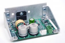
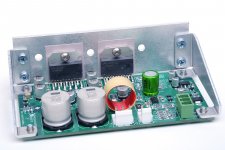
Pictures show the prototype builds of the two amp modules. The final version will feature Neurochrome Blue circuit boards and metal back LM3886es (LM3886T/NOPB, to be specific).
Tom
Attachments
Last edited:
I'd add a correction to that video. I didn't watch the full 45 minutes of it, but in the introduction he mentions that film caps have a polarity. That's incorrect. What they do have is two sheets of film rolled up with a sheet of dielectric in between. As result, one sheet of film/foil will be on the outside. You can reduce hum pickup (important in phono stages and tape circuits) by grounding the outer foil in cases where the caps connect to ground. In those cases, there's usually a marking on the package to indicate which lead is connected to the outer foil.
When in doubt, check the manufacturer's data sheet.
For the capacitor in question in the Modulus-86, there is no polarity. It can be installed either way.
Tom
When in doubt, check the manufacturer's data sheet.
For the capacitor in question in the Modulus-86, there is no polarity. It can be installed either way.
Tom
Yes, that's the theory, but what that video shows is that these indications are often wrong. If that is really the case, it looks quite surprising to me that no one else had ever noticed this behaviour. Looks quite "suspicious" to me at the very least.In those cases, there's usually a marking on the package to indicate which lead is connected to the outer foil.
@asuslover, welcome.
@tomchr, about that video also will guess we go in small shoes here regarding application of modern small footprint circuits as your modules")
Many years ago myself diy some tube guitar amps including overdrive stages that is not especially silent as is, maybe that application will benefit a recheck of how coupling caps are wired up.
@tomchr, about that video also will guess we go in small shoes here regarding application of modern small footprint circuits as your modules
Many years ago myself diy some tube guitar amps including overdrive stages that is not especially silent as is, maybe that application will benefit a recheck of how coupling caps are wired up.
Attachments
Last edited:
Thankfully, you don't have to worry about any of this kind of stuff with the circuits I design. I'll never design a circuit that requires you to perform experiments in order to get the component orientation correct. That's simply not a production flow. I design circuits that can be put into mass production. That makes them much easier for the DIYer to build.
Tom
Tom
Hi Tom, have you ever tried running any of the Modulus series into a dead short ?
I run my Mod 86 Parallel bridged mono's into Quad 989 ESL's and they sound great.
I have bought a pair of Quad 63 ESL's - to play with. There is an R/C on the input terminal which appears to be there in case the clamp shuts down and presents a short to the amplifier.
(R15/C25) https://www.quadesl.com/modernRefs/63schemLate.jpg
The first thing I wish to try is removing these cheap components from the signal path. Though there is little chance of my driving beyond the 40V clamp limit I just wondered what your thoughts were in a worst case scenario for the amps.
Especially as I only have 2 spare Lm 4780's.
Hi Tom, have you ever tried running any of the Modulus series into a dead short ?
I don't see a point of driving a short circuit. I make amplifiers. Not welders.
1 Ω is as close as I've come (by accident with the MOD686). I mostly test with 8 Ω and 4 Ω. I occasionally throw on a 2 Ω load as a sanity check.I also check with capacitive load. 8 Ω || 1 nF - 8 Ω || 1 uF.
I run my Mod 86 Parallel bridged mono's into Quad 989 ESL's and they sound great.
"Mod 86 Parallel bridged"? Are you running four Modulus-86 boards in a bridge/parallel? Or two Parallel-86 in a bridge? I'm thinking the latter.
I have bought a pair of Quad 63 ESL's - to play with. There is an R/C on the input terminal which appears to be there in case the clamp shuts down and presents a short to the amplifier.
(R15/C25) https://www.quadesl.com/modernRefs/63schemLate.jpg
1.5 Ω || 220 uF in series with a TRIAC. That's not nice. I don't think that TRIAC is a clamp, by the way. I haven't analyzed the 555 timer IC circuit that drives the TRIAC in detail, but it looks like a monostable flip-flop. My guess is that it shorts the input to the speaker while the HV builds up.
The first thing I wish to try is removing these cheap components from the signal path.
Why not replace them with better ones then? You probably need those to get the impedance right for the transformers anyway.
Especially as I only have 2 spare Lm 4780's.
Time for the MOD286...
hi folks iv got a couple of 24 volt meanwells i wish to use is there any drawbacks to using boost converter to step up to 28v
Why not just connect the Modulus-86 to the ±24 V? You'll get about 30 W into 8 Ω and roughly twice that into 4 Ω if your supplies can supply enough current.
Tom
Nope. Film capacitors are not polarized.
Passives such as resistors and film/ceramic/mica capacitors are not polarized. I generally install them such that they are all easy to read for verification and troubleshooting.
Semiconductors and electrolytic and tantalum capacitors are polarized, thus, must be installed following the markings on the board.
Note that some believe passive components "sound better" when oriented one way or another. To the best of my knowledge, there is no science to back up these claims.
Tom
Capacitors that are wound such that there is an inner foil connected to one lead and an outer foil connected to the other have differing noise characteristics. You cannot go by things like the direction of printing because when caps are manufactured they are not lined up in rows like little soldiers, but instead binned between manufacture and printing. So the outer foil is essentially random as far as the printing goes.
It is said that the outer foil used to be marked on caps with a bar at one end, but if that was ever true, it changed in the 1950's with different manufacturing equipment. The bar was retained (why replace a perfectly good cap marking machine?) but meant nothing.
In-circuit the outer foil should face the lower impedance side of the circuit. That provides the lowest noise performance.
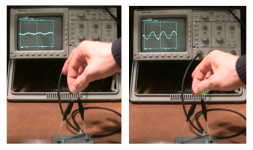
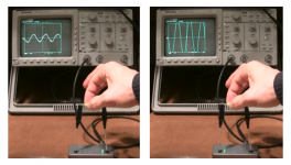
You can determine which lead is attached to the outer foil with a test apparatus, or with a 'Scope. The procedure is, basically, using your body, touch the cap and note the noise level; one orientation will be noticeably lower noise. Your body acts like an RF antenna.
The reason is the outer foil acts as a shield.
Electrically there is no difference, so other capacitor-related values will be identical either orientation with non-polarized caps.
Manufacturing of consumer electronics almost certainly has no patience for such testing and assembly, but we're DIY nerds, who take a bit longer to build an amplifier than Pioneer or BOSE does. So I think it's OK, or at least understandable, that we obsess over these details, if only to help us sleep at night ;-)
Last edited:
What happens if the output is short circuited by accident?I don't see a point of driving a short circuit. I make amplifiers. Not welders.
Tom
- Home
- Amplifiers
- Chip Amps
- Modulus-86 build thread