The screen/shield carries the interference current between the chassis.The received wisdom is that you should connect pin 1 of the XLR input socket to the chassis (using as short a path as possible). However, what should one do if you decide to not have an XLR socket and instead run your balanced input cable direct to the PCB ? A further complication; I may make my enclosure out of wood and other materials so that the only metal will be the heatsinks.
The screen/shield gets connected to the chassis at both ends.
The two signal wires pass straight through (at both ends) to the PCBs.
If you add a screen inside the chassis, then it too should be connected to the chassis at the pass through end. Because the only significant interference internally are the emi emissions of the amplifier and it's PSU you could try not connecting the PCB end of that internal screen, since the impedance at these lower frequencies and the short length between chassis and PCB will not seriously impede passing the interference to the one end at chassis. If you were to add a pigtail (to chassis) at the PCB end, that would just add to the impedance that the interference has to pass across.
That brings me back to your original question.
If you bring a screen/shield with interference through a hole in the chassis, you are bringing that interference inside the chassis. I can't believe that is good. It seems better to attenuate that at the chassis entry point.
Last edited:
I don't think you have the training and experience to design and build a ClassII product.I have no earth on my BPBP, there is no box at all and I wire that directly into the input on the Mod86 (which takes wires not sockets) so there's no earth there either.
That leaves you with no alternative but to build a ClassI product.
ClassI requires a properly connected Protective Earth.
This PE takes any Fault Current that gets on to any conductive part back to the mains distribution board. It is this PE route that blows the mains fuse if there is a catastrophic fault inside your build.
There is another advantage to using a PE.
The RCD/RCCB in your distribution board fusebox compares the current flow out of Live to current returning via Neutral. If this difference is above the set limit of the detector, the RCD/RCCB turns off the power.
This "escaping" current could generate a high voltage on some exposed, but semi-insulated conductive parts. The PE reduces the exposed component voltage to a level you may not even be aware of and saves you or anyone else from feeling the "tingling" of leakage current.
Use a PE that is connected to the main metal part of the Build AND connect ALL exposed conductive parts/components to this protected metalwork.
Metal bits that can be touched by a user should be grounded to mains earth.
That's a safety thing.
Tom
That's a safety thing.
Tom
Metal bits that can be touched by a user should be grounded to mains earth.
That's a safety thing.
Tom
Yes I fully intending to ground the heatsinks. It was the balanced cable shield I was thinking about.
The screen/shield carries the interference current between the chassis.
The screen/shield gets connected to the chassis at both ends.
So where does any 'collected ' interference end up ?
The screen/shield gets connected to the chassis at both ends.
So where does any 'collected ' interference end up ?
into the chassis and thence to "earth": the BIG earth that we stand on by the almost infinite ground plane. By capacitance between the chassis and "earth".
Lets assume my chassis is all metal and that I want to connect the shield of the balanced cable as it enters the chassis ( as recommended), but I still want to avoid having an XLR input connector. Is there anything wrong with breaking into the cable shield at the point the cable enters the chassis and connecting the shield to the chassis at that point? Unless I'm missing something that is doing exactly the same as connecting pin 1 of an XLR input connector to the chassis. Yes?The screen/shield carries the interference current between the chassis.
The screen/shield gets connected to the chassis at both ends.
The two signal wires pass straight through (at both ends) to the PCBs.
If you add a screen inside the chassis, then it too should be connected to the chassis at the pass through end. Because the only significant interference internally are the emi emissions of the amplifier and it's PSU you could try not connecting the PCB end of that internal screen, since the impedance at these lower frequencies and the short length between chassis and PCB will not seriously impede passing the interference to the one end at chassis. If you were to add a pigtail (to chassis) at the PCB end, that would just add to the impedance that the interference has to pass across.
That brings me back to your original question.
If you bring a screen/shield with interference through a hole in the chassis, you are bringing that interference inside the chassis. I can't believe that is good. It seems better to attenuate that at the chassis entry point.
Dunno the name, search goldmund chassis clone.
Andrew, though my amp is literally laid out without a chassis, the heatsink the amps are mounted on is earthed back to the iec socket in the box the transformer sits in with a suitably thick wire. The iec socket even has a fuse...
I was having a joke with Ian re my views on anything less than a full Metal Jacket for a finished bit of hifi. He knows my views on wood in cases all too well.
While it may not be super clear in the documentation, pin 1 of the XLR connects directly to the chassis. From there, continue the shield to pin 1 of the input connector on the Modulus-86 board. This connection is needed for the RF input filter.
In the ideal world, the RF filter would be integrated into the XLR connector. What's shown in the design documentation is the best I can do while keeping all the components on the PCB.
Tom
In the ideal world, the RF filter would be integrated into the XLR connector. What's shown in the design documentation is the best I can do while keeping all the components on the PCB.
Tom
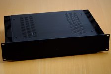
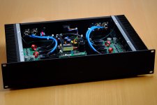
My turn to build. This time four channels of Modulus-286 powered by a Connex SMPS300RE. Built for a client who needed a demo amp for his high-end speakers.
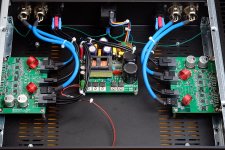
Each Modulus-286 board is a stereo Modulus-86. In the MOD286 I lowered the noise floor a tad, hence, was able to improve the THD+N numbers a bit.
You can run the two channels in parallel by adding a couple of resistors to the board.
In stereo, the MOD286 provides 2x40 W (8 Ω), 2x65 W (4 Ω).
In mono (parallel) mode, the MOD286 provides 1x60 W (8 Ω), 1x100 W (4 Ω).
You can read more here: Neurochrome :: Modulus-286
The boards shown here are the prototype boards. The final revision is underway via FedEx and should be on my doorstep by Tuesday. I've opened up for orders (here). The introductory sale ends January 6th.
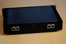
The chassis is from ModuShop. You can get them through the DIY Audio Store as well.
Tom
Each Modulus-286 board is a stereo Modulus-86. In the MOD286 I lowered the noise floor a tad, hence, was able to improve the THD+N numbers a bit.
You can run the two channels in parallel by adding a couple of resistors to the board.
In stereo, the MOD286 provides 2x40 W (8 Ω), 2x65 W (4 Ω).
In mono (parallel) mode, the MOD286 provides 1x60 W (8 Ω), 1x100 W (4 Ω).
You can read more here: Neurochrome :: Modulus-286
The boards shown here are the prototype boards. The final revision is underway via FedEx and should be on my doorstep by Tuesday. I've opened up for orders (here). The introductory sale ends January 6th.
The chassis is from ModuShop. You can get them through the DIY Audio Store as well.
Tom
Attachments
Tom,
Fantastic work as always. While proof reading your Modulus-286 webpage, I noticed one anomaly. Do a search for Modulus-86 , and for every utterance, depending on context, you may want to replace it with Modulus-286. Particularly look at the "Performance Characterization" section and below, including the block diagram.
Also at this link: http://www.neurochrome.com/product/modulus-286/ ;scroll to the third bullet point, and change 8 ohms to 4 ohms and vice versa. Then the mono output powers make sense.
Best,
Anand.
Last edited:
Dang! You're fast. I wasn't even done updating the site. 🙂 Thanks for the proof read. I just finished updating the site. New plots (should say MOD286 PROTO in the title). Text tweaks.
Nice catch on the product page power numbers.
If you don't see the changes, please hit reload in your browser.
Thanks again.
Tom
Nice catch on the product page power numbers.
If you don't see the changes, please hit reload in your browser.
Thanks again.
Tom
The balanced interconnect shield does not need to be connected at the receive end (some experts suggest to never connect it). In any event to not connect the shield directly to the audio circuit common. I would say to never bring the shield into the enclosure, but does a wood or plastic box count as an enclosure?
Have you seen these?While it may not be super clear in the documentation, pin 1 of the XLR connects directly to the chassis. From there, continue the shield to pin 1 of the input connector on the Modulus-86 board. This connection is needed for the RF input filter.
In the ideal world, the RF filter would be integrated into the XLR connector. What's shown in the design documentation is the best I can do while keeping all the components on the PCB.
Tom
EMC Series - Neutrik
The balanced interconnect shield does not need to be connected at the receive end (some experts suggest to never connect it).
The shield does need to be connected on the Modulus-86 (and -286) as it terminates the RF input filter. If you move those components to the XLR socket pins, you can terminate pin 1 at the chassis and leave the pin 1 connection to the PCB disconnected.
There's considerable debate on the pin 1 connection. The authoritative guide is AES48-2005.
Have you seen these?
Yeah. They're neat. Overkill for home audio but very neat regardless.
Tom
the differential mode interference is across the Cold and Hot Signal wires. This can be filtered as the cable enters the enclosure and/or as the signal enters the PCB.
The common mode interference from the pair of Signal wires to "Earth" should be filtered as the cable arrives at the enclosure. This is what the Neutrik "EMC" was designed to do: filter BEFORE the interference enters the enclosure.
The common mode interference from the pair of Signal wires to "Earth" should be filtered as the cable arrives at the enclosure. This is what the Neutrik "EMC" was designed to do: filter BEFORE the interference enters the enclosure.
I agree. I like the Neutrik EMC series. I just find them to be overkill for home hifi. Also note that any holes in the chassis will allow RF to enter the chassis. If you have ventilation holes or slots in the chassis, all this talk about EMC and RFI is (mostly) pointless.
Tom
Tom
The size of the hole determines what frequencies can easily pass through.
Thousands of 3mm diameter holes will attenuate most of the GHz that pollute our homes.
Long slots upto around 300mm long allow much of this HF to pass into our enclosures.
If the XLR socket is in electrical contact around the perimeter of the socket case then there is effectively no hole for the interference to pass through.
Great work on the amp, Tom!
I'm guessing that you're running the thing from 32V rails. Can you give me a good idea how hot the sinks got on idle and max dissipation?
I'm half-thinking of putting a 286 and your SMPS board in a small 1U enclosure and see what can I do thermally. Would make a really neat desktop speaker amp.
I'm guessing that you're running the thing from 32V rails. Can you give me a good idea how hot the sinks got on idle and max dissipation?
I'm half-thinking of putting a 286 and your SMPS board in a small 1U enclosure and see what can I do thermally. Would make a really neat desktop speaker amp.
- Home
- Amplifiers
- Chip Amps
- Modulus-86 build thread