Hi guys, girls and gurus alike.
I am in the proces of building my very first real stereo amplifier with the lm3875 chip.
Both powersuplys are finnished and tested same goes for the one amplifier board.
I have had it conectet without any erthing just for a test with my cellphone as signal device. It works and sounds beautiful")
But the time has come to the making of the second channel board, and trouble have arrised regarding erthing and grounding (the question without answer )
I have read and read, and got somewhat smarter but also a little confused?
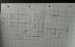
Therfore my question is: Will this grounding/earthing sheeme work?
I am in the proces of building my very first real stereo amplifier with the lm3875 chip.
Both powersuplys are finnished and tested same goes for the one amplifier board.
I have had it conectet without any erthing just for a test with my cellphone as signal device. It works and sounds beautiful
But the time has come to the making of the second channel board, and trouble have arrised regarding erthing and grounding (the question without answer
)I have read and read, and got somewhat smarter but also a little confused?
Therfore my question is: Will this grounding/earthing sheeme work?
Attachments
Uhh. another question.
Say i decide to mount the lot in a pvc chassis (funding is tight when studying)
Does the safety ground/earth wire have to be connected to ground?
My current amp is class 2 and thus not connected to earth.
I've read somewhere that ground loops could occur when class1 and class2 devices are interconnected.
My computer that i play my music from is connected to mains earth and interconnected to my amp, and there is no problem.
not quite.
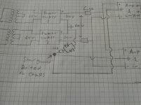
the 10R 10 W resistor is in parallel with the diodes ( sorry for me being unclear). I would move the circuit grounds away from safety earth and connect to power supply common instead.
Then, you have all grounds at the same potential, as you do in the original drawing, but this is lifted from safety earth so that any noise on earth is isolated.
Last edited:
That makes good sense. And thanks for the swift reply
Could i instead of the 10R resistor use the really nice looking 12R on the picture? It should be good for 10W.
also. Would two 1N5408 diodes work? They can handle 3A, where i get 2,5A in a fault condition if i use the 12R resistor. Ignoring Vdrop over the diode of corse.
I have updated the drawing.
Could i instead of the 10R resistor use the really nice looking 12R on the picture? It should be good for 10W.
also. Would two 1N5408 diodes work? They can handle 3A, where i get 2,5A in a fault condition if i use the 12R resistor. Ignoring Vdrop over the diode of corse.
I have updated the drawing.
Attachments
AndrewT: you mean a phase to chasis. yeah. that will be fused though.
I meant rail to chassis, but my calculations are wrong. I calculated with the 10/12 ohm resistor in series resulting in 2.5/3 A. But now it should be in parallel with the diodes the circuit will short and hopefully blow the fuse.
Correct me if i am wrong.
I meant rail to chassis, but my calculations are wrong. I calculated with the 10/12 ohm resistor in series resulting in 2.5/3 A. But now it should be in parallel with the diodes the circuit will short and hopefully blow the fuse.
Correct me if i am wrong.
I would:
1. Build the mains / primary side to IEC Class II standards (double insulated, blah blah)
2. Keep signal circuitry completely separate and insulated from chassis
3. Connect chassis to safety earth (and transformer housing to chassis if applicable)
In order to fault this concept, you'd need a transformer primary to secondary isolation fault - but a Class II appliance won't protect you from that either. The majority of mass-market amplifiers and receivers are Class II devices, never heard of them being a safety hazard. Transformers must be pretty good.
Having a chassis on safety earth ought to be even better, as that would always be safe to touch (outlet miswiring excepted, obviously). The need for isolation admittedly makes things a tad cumbersome (commercial units tend to use the back panel as low-level "star ground", apparently), but that part should be manageable with the right terminals and jacks.
The 10R suggested may not be low enough to eliminate ground loops to a satisfying degree when sources with "hard-earthed" grounds are connected.
Connecting the secondary to chassis will not complete a circuit. No additional current can flow in an incomplete circuit.
Therefore a fuse cannot blow.
If one side of a secondary is already connected to Chassis and the other side of the secondary connects (without a resistor) to the Chassis then that completes a new circuit.
If the current that flows is high enough to significantly load the transformer then the Mains Fuse may blow. It depends on the fuse rating and the primary current flowing.
AndrewT: i totally agree, Thoug i think you misunderstood me. I meant the output from one of the powersuplys shorting to chassis meaning one of the rail fuses will blow
I have two noratel 80 VA transformers that i would use. A label on them says they should be protected by a 4 A mains fuse fuse. If both of the secondarys on one transformer short to chassis it will blow. Right? Assuming the tranny can deliver the current of corse.
sgrossklass: Problem is just that i don't have the means to make it a class 2 apparatus because of my design idea for the chassis. And it just seems easier making it class 1.
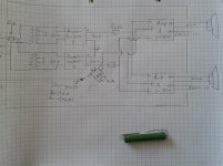
Do you think it will pose any real problems? The ground bus/signal ground is isolated from chassis/PE with the diode-resistor bridge shown on the last drawing.
The way i see it is that i am protected from phase to chassis shorts by my mains fuse. and if that fails my HPFI breaker would trip. Furthermore i am protected from rail to chassis shorts by the rail fuses. And two secondarys to chassis will blow the mains fuse.
Cant see any real safety issues? correct me if i am wrong?
I might try and connect it all up tonight if there is no concerns. I mean, it can't blow my hands off?
I have two noratel 80 VA transformers that i would use. A label on them says they should be protected by a 4 A mains fuse fuse. If both of the secondarys on one transformer short to chassis it will blow. Right? Assuming the tranny can deliver the current of corse.
sgrossklass: Problem is just that i don't have the means to make it a class 2 apparatus because of my design idea for the chassis. And it just seems easier making it class 1.
Do you think it will pose any real problems? The ground bus/signal ground is isolated from chassis/PE with the diode-resistor bridge shown on the last drawing.
The way i see it is that i am protected from phase to chassis shorts by my mains fuse. and if that fails my HPFI breaker would trip. Furthermore i am protected from rail to chassis shorts by the rail fuses. And two secondarys to chassis will blow the mains fuse.
Cant see any real safety issues? correct me if i am wrong?
I might try and connect it all up tonight if there is no concerns. I mean, it can't blow my hands off?
Sadly today it was confirmed that the earthing scheme does not work. There was lots of humm. Would the cl60 thermistor solution solve the problem?
Without the earth though, the lot performed beautiful.
If i connect safety earth to chassis and holds the ground completely isolated no humm will occur. Still the rail fuses will blow if ground to rail shorts occur.
After reading some pages in stærkstrømsbekendelsen 6 (the danish guidelines for electrical installations) I've found this solution both legal and secure? Same as sgrossklass suggested.
Any electricians that can confirm?
Last edited:
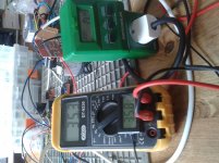
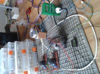
A picture of the proces.
This was connected without the earth so i could hear it on my main speakers. I was as loud as i feel i can play because of neighbors.
One channel in use. rail voltage, heatsink temp and watt use was measured.
This was connected without the earth so i could hear it on my main speakers. I was as loud as i feel i can play because of neighbors.
One channel in use. rail voltage, heatsink temp and watt use was measured.
Attachments
Last edited:
Why does this always get so complicated?
The Protective Earth / Safety Ground wire connects to the chassis near the power cord entrance. End of story.
All of the power supply commons and all the audio circuit commons connect together at the Main Audio Ground (MAG) point and this point connects to the chassis near the Input/Output jacks.
The Protective Earth / Safety Ground wire connects to the chassis near the power cord entrance. End of story.
All of the power supply commons and all the audio circuit commons connect together at the Main Audio Ground (MAG) point and this point connects to the chassis near the Input/Output jacks.
Why does this always get so complicated
It gets complicated when i does not work. connecting pe to the ground bus results in lots of hum. At least where i live.
Why would you connect the PE/SG to anything but the chassis?
Just what is your 'ground bus'?
To do some serious troubleshooting, start at about page 99 of this Bill Whitlock paper.
"An Overview of Audio System Grounding and Interfacing"
by
Bill Whitlock, President
Jensen Transformers, Inc.
Life Fellow, Audio Engineering Society
Life Senior Member, Institute of Electrical & Electronic Engineers
http://centralindianaaes.files.wordpress.com/2012/09/indy-aes-2012-seminar-w-notes-v1-0.pdf
Why would you connect the PE/SG to anything but the chassis?
Just what is your 'ground bus'?
To do some serious troubleshooting, start at about page 99 of this Bill Whitlock paper.
"An Overview of Audio System Grounding and Interfacing"
by
Bill Whitlock, President
Jensen Transformers, Inc.
Life Fellow, Audio Engineering Society
Life Senior Member, Institute of Electrical & Electronic Engineers
http://centralindianaaes.files.wordpress.com/2012/09/indy-aes-2012-seminar-w-notes-v1-0.pdf
I would not.
By ground bus i mean ground from the supply's witch also will be ground on the amp boards.
Thanks for the source. I'll dig into it right away.
- Status
- This old topic is closed. If you want to reopen this topic, contact a moderator using the "Report Post" button.
- Home
- Amplifiers
- Chip Amps
- Will this grounding scheme work?