NO !!!!
the The Mains cable should have a third wire.
This third wire is Protective Earth (PE).
Bolt or mechanically fix the PE directly to Chassis PERMANENTLY.
This creates the Safety Earth.
This is what prevents you killing yourself and any operators that touch your equipment !!!!!!
the The Mains cable should have a third wire.
This third wire is Protective Earth (PE).
Bolt or mechanically fix the PE directly to Chassis PERMANENTLY.
This creates the Safety Earth.
This is what prevents you killing yourself and any operators that touch your equipment !!!!!!
The Protective Earth / Safety Ground wire connects to the chassis near the power cord entrance. End of story.
How many times do you need to be told ?Seconded.
Also protective earth should have a direct connection, no diodes, no resistors nothing just a low impedance thick wire, anything else is dangerous.
Last edited:
Seconded.
Also protective earth should have a direct connection, no diodes, no resistors nothing just a low impedance thick wire, anything else is dangerous.
agreed...this is what i do in my amp builds...

Now that you have confirmed that you have connected the Safety Earth to Protective Earth, i.e. Chassis to PE.
You now have to comply with the next requirement.
All exposed and/or external conductive parts to be connected to the protected Chassis.
I will mount it in a aluminium pipe, wth a metal frontgrill and plastic back panel. Front panel will be connected to chassis.
Than there will be no other external parts being connected to chassis.
Speaker and rca jack grounds mountet on the back panel won't be connected to chassis. Problem?
Yes.Problem?
The barrel of an exposed RCA socket is an exposed conductive part.
It needs to be connected to Chassis.
A screw head on the underside of a chassis needs to be connected to Chassis.
Exposed speaker return metalwork needs to be connected to Chassis, even when the casing is insulating.
If you have young children around, then the far end of interconnects could be required to be connected to Chassis.
This is easiest and cheaply met by connecting ONE wire directly from Chassis to Main Audio Ground.
Have a look at the outside of any Class11 product. All the metal screws used to fix the panels together are buried down inside deep tunnels. This is to comply with "all exposed conductive parts".
Many are designed to fix panels together without any conductive parts simply to comply and to save money.
Last edited:
That means i can chose between being electrocuted or have a noisy useless amp.
Great.
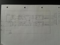
Say that i build the powersuply in one chassis, with the PE connected to chassis. Than have connectors with no external conductive parts being the positive, negative and ground supplying the amp's in their own chassis.
The chassis of the amp won't be connected to anything.
Great.
Say that i build the powersuply in one chassis, with the PE connected to chassis. Than have connectors with no external conductive parts being the positive, negative and ground supplying the amp's in their own chassis.
The chassis of the amp won't be connected to anything.
The umbilical connects the Mains powered PSU to the Amplifier Chassis.That means i can chose between being electrocuted or have a noisy useless amp.
Great.
Say that i build the powersuply in one chassis, with the PE connected to chassis. Than have connectors with no external conductive parts being the positive, negative and ground supplying the amp's in their own chassis.
The chassis of the amp won't be connected to anything.
There is a Thread from about 6 or 7years ago discussing this issue.
There have been many other Threads that were introduced by Members that did not read that very informative Thread.
- Status
- This old topic is closed. If you want to reopen this topic, contact a moderator using the "Report Post" button.
- Home
- Amplifiers
- Chip Amps
- Will this grounding scheme work?