Hello fellow audio enthusiasts!
I have a scooter sound system project in the process and I have run into a few problems! I have searched high and low for solutions and I have gotten so so many different answers and opinions. Heres what I'm trying to do
3 weeks ago I bought an electric scooter (The Raptor) and I have desperately been trying to figure out how to power my small 23w Sub that I took out of a 2.1 with sub PC speakers (Logitech Z4's). My first attempt literally almost killed me. I laugh at my major stupidity now but in all seriousness I could have died or at the least been seriously injured.Long story short I watched a video online on how to turn a car battery into a battery back up with a 12v cigarette lighter adapter. I then went out and got a 200w power inverter. I plugged in the speakers as is (in the original box). At first it worked awesome. My first test of a 20 minute trip went smooth. However my 2nd trip of an hour went horribly bad! The battery caught on fire while I was driving and caught my back trunk compartment on fire. Lets just say my bike no longer has a trunk lol.
I have been doing some research on the SLA batteries that my bike uses but I'm told that I would only get at most and hour of play time out of a charge. Which is actually pretty good for me since I never really ride the bike for "hours" straight.
Anyways now that you have a bit of background to what I have been up to here is what I have done so far and where I'm at.
I decided to try and power the full range speakers (both are 17w a piece) with an amp from a pair of USB powered pc speakers. So far they work fantastic. I bought a USB battery back up @ 3.6v and 2800 mha to power it on my bike. I took out the sub speaker and amp from inside the sub box.
Here is where I need help. I was hoping to be able to use the chips and diodes etc on the board I have and remake a new amp board specifically just to power the 23w sub. I have a better then average skills with a solder iron and I can follow direction with great precision but when it comes to knowing the details of what each chip and diode does is beyond me. I have no clue in where to begin to make a new amp board.
If someone could take a look at what I have (Pictures at bottom) and possibly help me find the proper instructions on how to build the amp and maybe any extra parts/materials I will need, so that it wont take a ton of power to run I would be so ever grateful!
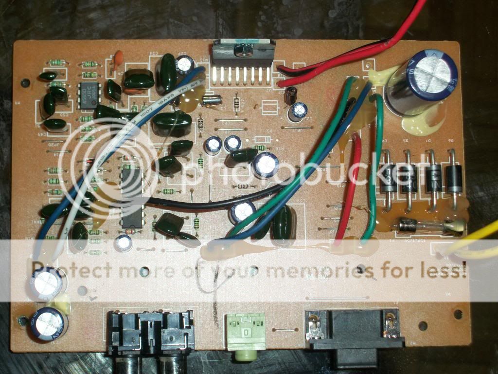
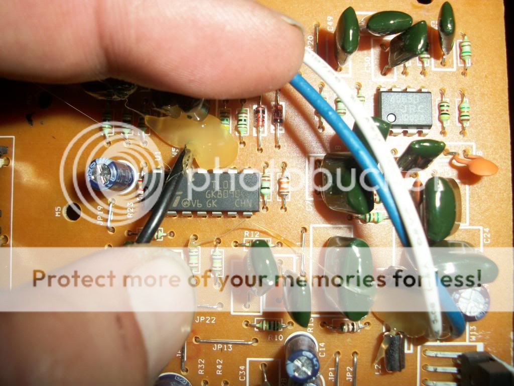
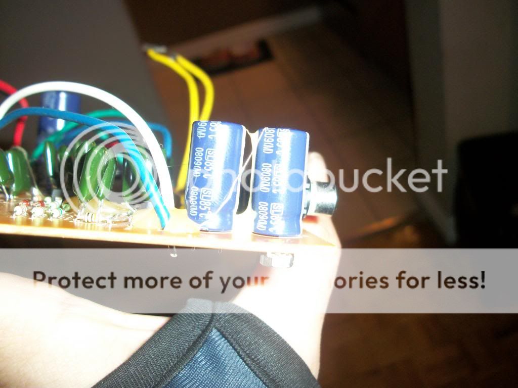
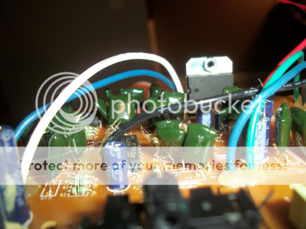
FULL AMP BOARD VIEW:
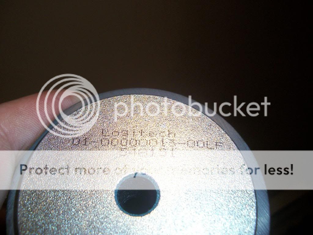
SUBWOOFER SERIAL NUMBER:
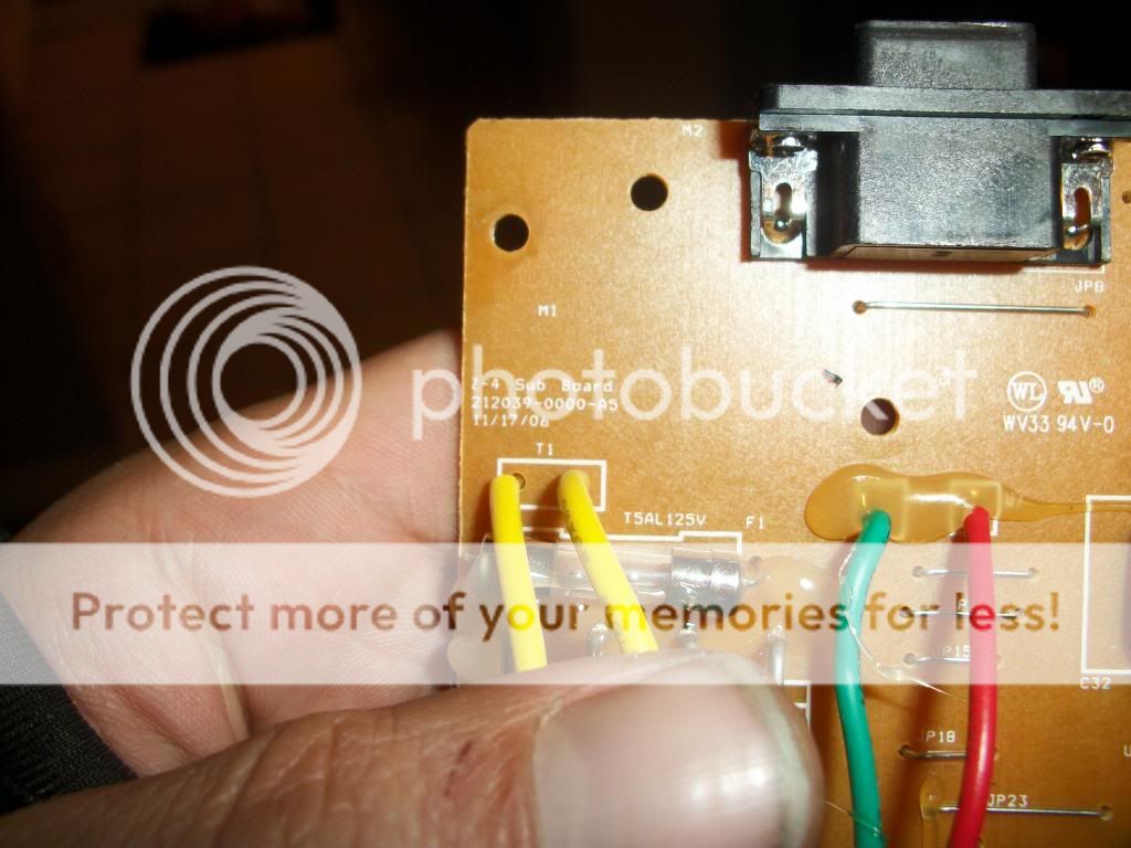
AMP BOARD ID:
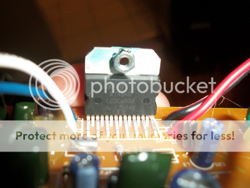
STA540 Amp Chip:
JRC 45650 Amp Chip:
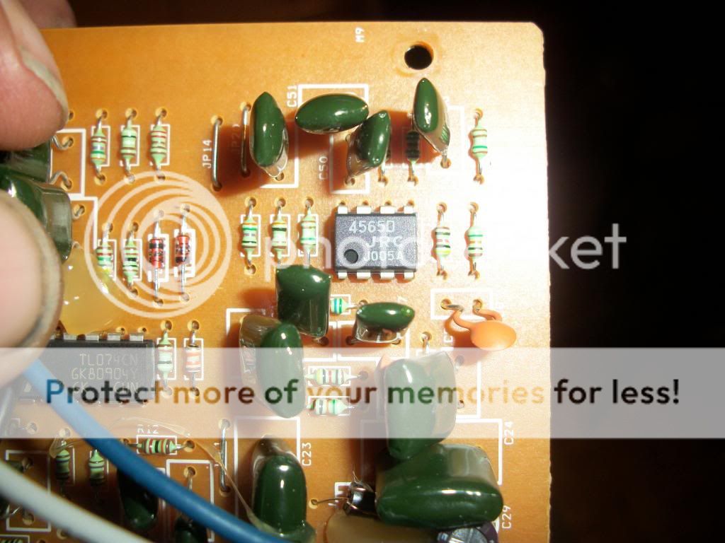
TL074CN Amp Chip:
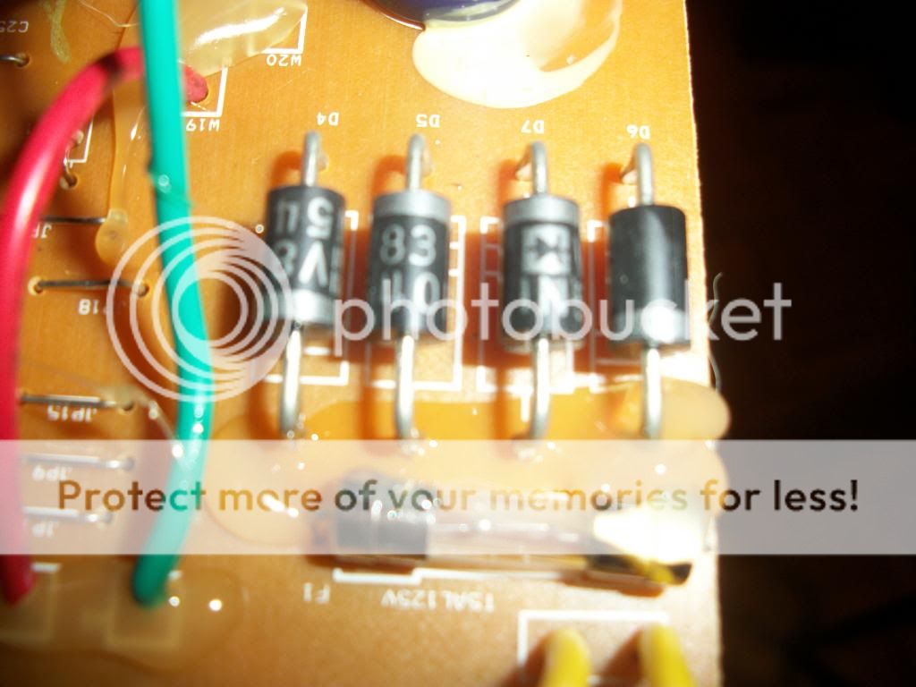
DIODES ETC..
Any help is greatly greatly appreciated! Thanks so much!
I have a scooter sound system project in the process and I have run into a few problems! I have searched high and low for solutions and I have gotten so so many different answers and opinions. Heres what I'm trying to do
3 weeks ago I bought an electric scooter (The Raptor) and I have desperately been trying to figure out how to power my small 23w Sub that I took out of a 2.1 with sub PC speakers (Logitech Z4's). My first attempt literally almost killed me. I laugh at my major stupidity now but in all seriousness I could have died or at the least been seriously injured.Long story short I watched a video online on how to turn a car battery into a battery back up with a 12v cigarette lighter adapter. I then went out and got a 200w power inverter. I plugged in the speakers as is (in the original box). At first it worked awesome. My first test of a 20 minute trip went smooth. However my 2nd trip of an hour went horribly bad! The battery caught on fire while I was driving and caught my back trunk compartment on fire. Lets just say my bike no longer has a trunk lol.
I have been doing some research on the SLA batteries that my bike uses but I'm told that I would only get at most and hour of play time out of a charge. Which is actually pretty good for me since I never really ride the bike for "hours" straight.
Anyways now that you have a bit of background to what I have been up to here is what I have done so far and where I'm at.
I decided to try and power the full range speakers (both are 17w a piece) with an amp from a pair of USB powered pc speakers. So far they work fantastic. I bought a USB battery back up @ 3.6v and 2800 mha to power it on my bike. I took out the sub speaker and amp from inside the sub box.
Here is where I need help. I was hoping to be able to use the chips and diodes etc on the board I have and remake a new amp board specifically just to power the 23w sub. I have a better then average skills with a solder iron and I can follow direction with great precision but when it comes to knowing the details of what each chip and diode does is beyond me. I have no clue in where to begin to make a new amp board.
If someone could take a look at what I have (Pictures at bottom) and possibly help me find the proper instructions on how to build the amp and maybe any extra parts/materials I will need, so that it wont take a ton of power to run I would be so ever grateful!
FULL AMP BOARD VIEW:
SUBWOOFER SERIAL NUMBER:
AMP BOARD ID:
STA540 Amp Chip:
JRC 45650 Amp Chip:
TL074CN Amp Chip:
DIODES ETC..
Any help is greatly greatly appreciated! Thanks so much!
STA540 is a quad power amplifier and can be used to drive minimum two speakers in bridge mode. So you will have to use some other dual power amp chip for connecting a single sub. Using the chip partially will stress it.
U want to make only a sub-amp with this board.
You can use the same board for its other functions and add a power amp of your choice.
How to...
Download the datasheet for STA540. Now find out which (pins)amps drive the subwoofer. Trace back the corresponing input pin to one of the two(out of 4) amps where the signal is fed. Trace further back from which IC this signal come from. It is mostly the 8 pin IC. This circuit is a low pass filter that drives the sub woofer power amp.
All the rest will remain the same.
Find one dual power amp chip and construct it in bridge mode from the application on its datasheet.
Gajanan Phadte
I was hoping to be able to use the chips and diodes etc on the board I have and remake a new amp board specifically just to power the 23w sub. I have a better then average skills with a solder iron and I can follow direction with great precision but when it comes to knowing the details of what each chip and diode does is beyond me. I have no clue in where to begin to make a new amp board.
So let's begin!
Diodes - full wave rectifier
You don't need 'em because you have batteries which supply DC current
Capacitor- Yeah, probably that will serve: the capacitor after rectification has the purpose of levelling the peaks of diodes switching on/off; it has also the funcion of reservoir capacitor for keeping up with the music peaks ( high current demand)
Chips- Those are Op-Amps, not just "amps". The STA540 might be defined as a power op-amp.
The circuitations that are build "around" those chips are : input stage ( buffer); Left&right channel MIX and lowpass filter ( 074 ).
If the STA540 has four amplifiers inside, they'll be connected like : two in BTL for the sub; one for each channel with capacitor coupling ( it often permorms also the duty of high-pass filter for the speakers).
STA540 is a quad power amplifier and can be used to drive minimum two speakers in bridge mode. So you will have to use some other dual power amp chip for connecting a single sub. Using the chip partially will stress it.
U want to make only a sub-amp with this board.
You can use the same board for its other functions and add a power amp of your choice.
How to...
Download the datasheet for STA540. Now find out which (pins)amps drive the subwoofer. Trace back the corresponing input pin to one of the two(out of 4) amps where the signal is fed. Trace further back from which IC this signal come from. It is mostly the 8 pin IC. This circuit is a low pass filter that drives the sub woofer power amp.
All the rest will remain the same.
Find one dual power amp chip and construct it in bridge mode from the application on its datasheet.
Gajanan Phadte
Okay, so I actually already had the datasheets downloaded for all 3 chips. I have been able to figure out some of what you were instructing. Here is what I have so far..
AMP BOARD DIAGRAM:
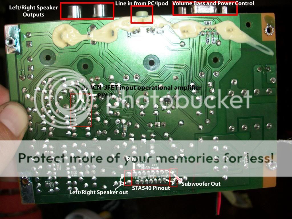
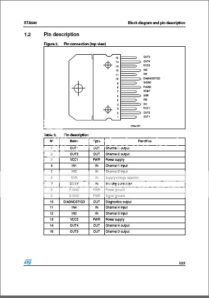
The Sub out is connected to Pins 14 and 15 of the STA540
STA540 PIN DIAGRAM:
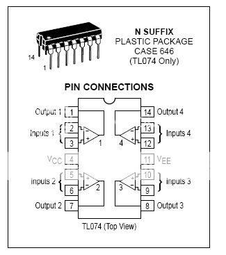
TL074CN PIN DIAGRAM:
I tried to trace where everything went but I got lost. What I was hoping is that I could be instructed on what chips/diodes/capacitors I needed off this board. I could then un-solder them off that board and create a smaller sub amp that is just spacific to the sub. This amp also ran off of a 110v wall socket so I figured that I will have to change around the diodes/resisters and fuse (fuse rates @ 125v 5A) to be able to properly power it by the 12v SLA battery...right?
The path is very easy if you are directed.
The last pins (14,15) are connected to the subwoofer and these are designated as out 3(channel 3 output) and out4(channel 4 output.
These pins are the outputs of the two(of4) power amps inside the chip.
Every power amp will also have an input if it has to be used as power amplifier.
The inputs for Ch3 and Ch4 are at pin 12 and 11 respectively.
One of these two pins will get the signal from the low pass filter made from one of the ICs(Op amp) and will invariably come from the output pin of an opamp, through a capacitor(mostly). Again same repetition...find the input that corresponds to that output.
In short, a low pass filter will pass lower frequencies only and a subwoofer needs only those.
Qs and doubts...ask
Gajanan Phadte
Uh eh ??
Now I realize.
Ok for extracting the power chip. That is quite a radical solution !
I might fail in doing that; the only mod I did was to eliminate the vol/s-by cable . Often these kind of devices are used by kids who literally play soccer with the sub box and most of the connections are broken / desoldered
Now I realize.
Ok for extracting the power chip. That is quite a radical solution !
I might fail in doing that; the only mod I did was to eliminate the vol/s-by cable . Often these kind of devices are used by kids who literally play soccer with the sub box
and most of the connections are broken / desolderedHe wants to use it only as a sub woofer amp.
So only connect the sub woofer. leave L and R outputs disconnected.
Does this board not already do what you want to build?
L + R + SUB. Or am I missing something?
So only connect the sub woofer. leave L and R outputs disconnected.
Hi Mark. I'm sorry that my block of text was a bit confusing to understand my goal here lol.
Long story short brother, This amp board belonged to a Logitech Z4 PC speaker system. I am trying to build a small sub amp that I can get to run as low as possible on power drain so that I can power the sub/amp by a 12v 9ah or 12ah SLA battery.
This in turn will be added to my electric scooter for a sound system.
The amp is currently set up to need a 110v wall plug as it's power source.
What I want to do is take ONLY the parts I need to run a subwoofer and then enable it to run properly off the SLA Battery.
I hope that was explained better. Sorry I'm not very "technical" in speech.
The path is very easy if you are directed.
The last pins (14,15) are connected to the subwoofer and these are designated as out 3(channel 3 output) and out4(channel 4 output.
These pins are the outputs of the two(of4) power amps inside the chip.
Every power amp will also have an input if it has to be used as power amplifier.
The inputs for Ch3 and Ch4 are at pin 12 and 11 respectively.
One of these two pins will get the signal from the low pass filter made from one of the ICs(Op amp) and will invariably come from the output pin of an opamp, through a capacitor(mostly). Again same repetition...find the input that corresponds to that output.
In short, a low pass filter will pass lower frequencies only and a subwoofer needs only those.
Qs and doubts...ask
Gajanan Phadte
Thank you, you have been of great assistance! I am working on this now.
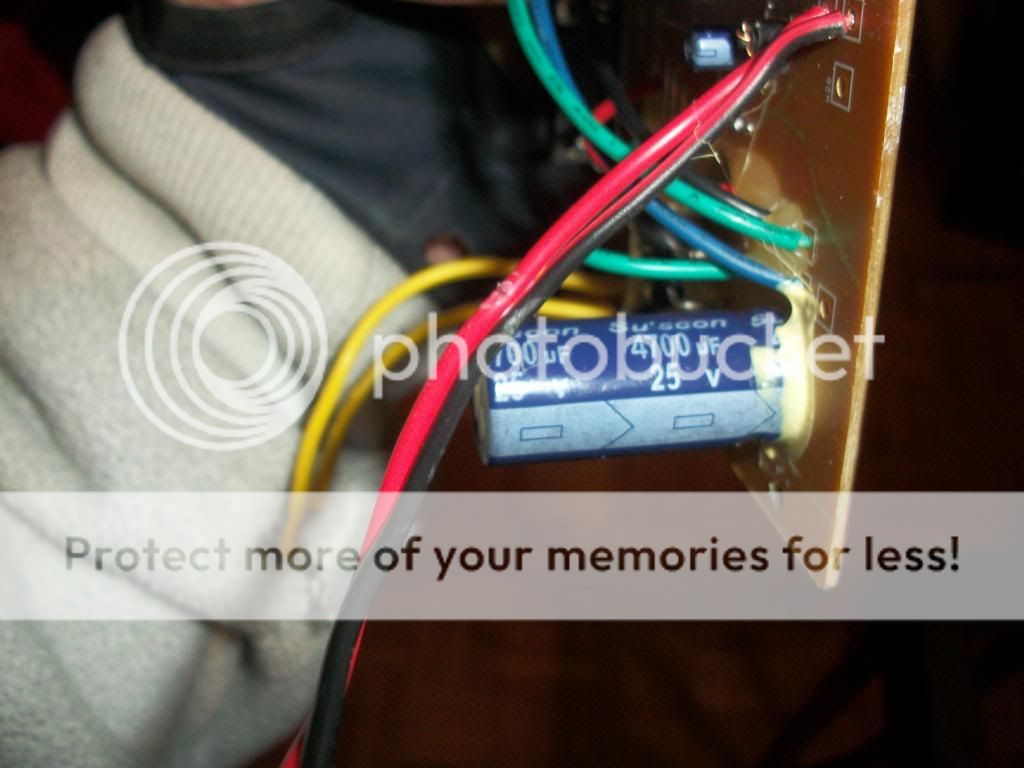
The transformer is still in the sub box.Are you sure its 110 V. Where is the transformer?
I just double checked it.
Input is 120v 60hz
output is 14.4v 1.6a
If you connect the two yellow power wires of the amp to your 12v battery. The voltage will be a bit lower but should work. The diodes will sort out the polarity. Don't forget to use the volume controller. You can also connect L and R speakers if you want.
Even though the fuse is a 125v 5a? will the 12v be able to run that? Also which one is + and -? Does + go into the fuse first and then out to the board?
Last edited:
Even though the fuse is a 125v 5a? will the 12v be able to run that? Also which one is + and -? Does + go into the fuse first and then out to the board?
Never mind I figured it out! Thanks for your help mark! That's ALOT simpler then what I was going to do LOL!
Great, glad to be able to help. The fuse voltage is just a maximum, its the amps (A) that is important. How does it sound? Do you need to build a new enclosure for the sub or will you use the old one?
Well my initial install failed because I noticed there was a diode disconnected so I had to take apart an older set of speakers. I have it all hooked up now on the Scooter. ITS AWESOME! The Sub is a bit "bad" but it works for what I need it for. I also plan on upgrading the sub and amp this summer. FYI I ended up buying a $60 Car battery jumper with a built in battery for 12v powering. A full charge will power my speakers and Amp for approx 5-6 hours which is WAY more then I need.
I'm just doing the finishing touches on my video I recorded of the before and after build. Once it is complete I will send you a link so you can see our work for yourself! BTW I sent you a shout out on the video =)
- Home
- Amplifiers
- Chip Amps
- Need some major help building a system!