my wife uses sketch for her interior design work. but i use protel 2.7 version its old one.. but i m soo used to to it that i can do my own footprints and double sided single side pcb layouts .. ( though manually but still)
i will look in to sprint... i was curious as to how you got the 3d thing .. i dont know hwo i could do it in protel 2.7... now protel is altium
i will look in to sprint... i was curious as to how you got the 3d thing .. i dont know hwo i could do it in protel 2.7... now protel is altium
Hi there
Your half way there then 😀 If your happy with protel/altium then stick with it. If it has no 'export as image' facility then just hit the 'Prt Scr' Key on your PC/Laptop (Print Screen) then just crop the resulting image down to the PCB outline.
I use 'The Gimp' for any post processing work and this has been very useful.
So once you have made your PCB image, as a jpg, go into sketchup and create a rectangle of the correct width and depth to match the PCB. Use the 'push pull tool' to make the rectangle 1.6mm thick.
Go to - File > Import. Change file type to .jpg, tick 'texture'. Select the image file and it will be linked to the cursor.
Click the lower left corner of the PCB then move the cursor to the upper right hand corner. The image will snap to the shap then click to fix.
Some times the image will appear to want to be laid at right angles to the 'PCB' Simply rotate the PCB then go pack to the import image and try again. It has been very useful. There is also a lot of components to be found in the sketchup warehouse online. I preferred to make my own though using data sheets as reference.
regards
Foo
Wiring:
A secondary winding to a KPBC3502 for V- to cap, to cable, to V- of BOTH reg boards.
A secondary winding to a KPBC3502 for V+ to cap, to cable, to V+ of BOTH reg boards.
A transformer needs Equal number of bridge rectifiers as it does secondary windings.
Both reg boards need v+ and v-
Error is: Splitter function shouldn't be at output of transformer--split for left/right should be at output of rectifiers.
P.S.
Error caused by: Previously the build had two transformers for dual mono and this used twice as many of smaller size rectifiers; however, since one transformer went missing, NOW we need to reduce the number of rectifiers (a caveat of reducing the number of transformers) to only 2 and double their strength (KBPC3502).
Compare:
Previous plans: 2 transformers with 4 KBPC1004
Current should: 1 transformer with 2 KBPC3502
Last edited:
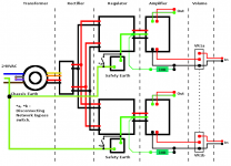
I love your "Chassis Earth Ground" terminology. That is so precise. Yes Chassis ground = earth ground.
The new schematic looks like a valid place to start. It seems a good representation of "virtual dual mono" wiring--the stereo width performance of monoblocs yet done with only one transformer.
Exact same length cables for right and for left is necessary for all grounding. When virtual dual mono, the right and the left need to be precisely identical in every way including cable lengths.
The schematic needs a mains fuse added series to the transformer primary winding. The purpose of the ground loop breakers are to blow that fuse when necessary, and so the fuse needs to be shown on that schematic.
Hello there
Still in limbo here. But the time has not been wasted...........Well I hope not 😀
For 'future' expansion I have been working on a 'source selector'. In essence I have spliced two circuits together which I found on the net.
One is a 'relay saver' the other is the selector circuit.
The relay saver, when activated, closes the relay. Once the relay is closed the mA are reduced by upto 50%. The relay stays on but at this reduced mA. This saves both power and heating of the relay coil.
The selector is based on a 4017 IC and a 4093 IC. The latter is set up to pulse the clock of the 4017 and detect when the activated switch has fired the attched relay and then disable the clock of the 4093 until another source button is pressed.
I've gone for four inputs but you could go upto 10 if you were so minded.
Each relay, DPDT, is wired to handle one pair of Inputs, Left and Right. Bearing in mind my intended set up I have kept the Left and Right grounds as seperate lines to keep to my wiring plans.
Still up in the air as such but when I have time I will breadboard this circuit and see how it goes.
regards
Foo
Attachments
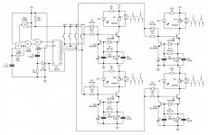
That circuit is like 90% of a discrete amp.
Instead, how about one 4 pole rotary dial?
At the output of the rotary, you can use a DPDT (switches only signal+) for a tape loop or you could use a 4PDT for tape loop.
P.S.
Did you make a dual mono preamp or did you decide on higher gain?
I was asking about the preamp, because these kind of controls are for preamps unless you don't have one.
Last edited:
- Status
- Not open for further replies.
- Home
- Amplifiers
- Chip Amps
- New amplifier...possibly..