Hi everyone,
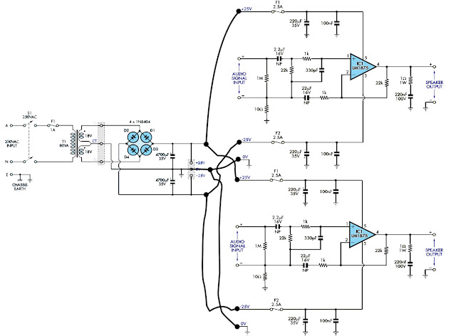
This forum seems to be very active a and helpful to novices. I have a question about lm1875 power supply. because I currently have an 18-0-18 6amps transformer(pls disregard the T1 value on the diagram). Can I use the circuit below for the tranny?

This forum seems to be very active a and helpful to novices. I have a question about lm1875 power supply. because I currently have an 18-0-18 6amps transformer(pls disregard the T1 value on the diagram). Can I use the circuit below for the tranny?
It ought to work okay, but since you only need 18-0-18 why create it twice? Just use a more robust bridge rectifier. Once.
Hi,
the dual amplifier (stereo/two channel) running from that common transformer has a common connection to ground.
Each amplifier will connect to ground via the PSU and again via the input interconnect.
These are big ground loops. You will get buzz and hum.
either use a dual secondary and dual bridge rectifiers and dual Disconnecting Networks or
use a centre tapped single dual polarity supply and connect all channels to the same ground.
Even following either of those advice routes and you may still get buzz and hum, but at a lower level.
I've done this without any problems, However The zero volts returns from both channels are to a point exactly central to the two half's of the power-supply.
My original reasoning for using separate rectifiers and cap bank for each channel was that I thought it would reduce channel crosstalk. As I never built a single bridge supply for the amp I can't say whether or not it really does make a difference.
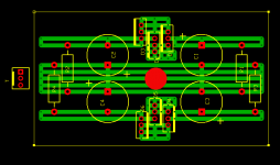
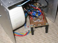
layout of the board is attached below, as well as an actual picture. The amp does have some very low level hum, but it is only possible to hear it with an ear right up against the speaker.
Tony.
My original reasoning for using separate rectifiers and cap bank for each channel was that I thought it would reduce channel crosstalk. As I never built a single bridge supply for the amp I can't say whether or not it really does make a difference.
layout of the board is attached below, as well as an actual picture. The amp does have some very low level hum, but it is only possible to hear it with an ear right up against the speaker.
Tony.
Attachments
Thanks for the responses. I just saw that power supply circuit at (url removed by moderators) and thought I might use a single transformer for two channels.
The original power supply circuit is this
(link removed by moderators)
and the amp's cicuit is this
(link removed by moderators)
Would a separate transformer for each channel be better?
The original power supply circuit is this
(link removed by moderators)
and the amp's cicuit is this
(link removed by moderators)
Would a separate transformer for each channel be better?

An article
Hum and ground is a complex topic. You might want to read this article about http://www.diyaudio.com/forums/diya...ponent-grounding-interconnection.html?garpg=5
Hum and ground is a complex topic. You might want to read this article about http://www.diyaudio.com/forums/diya...ponent-grounding-interconnection.html?garpg=5
Thanks for the responses. I just saw that power supply circuit at (URL removed by moderators) and thought I might use a single transformer for two channels.
The original power supply circuit is this
and the amp's circuit is this
Would a separate transformer for each channel be better?
Hi Chricket,
Here's the original source of this amp.
Silicon Chip Online - Schoolies Amp
BTW: The original article only describes a mono amp.
BTW: These people seem to be ripping off Silicon Chip. The pictures they reproduce are exactly those published in the SC article except any reference to "Silicon Chip" has been erased. 🙁
regards
Last edited:
Greg, is the power supply in the original post also SC copyright? I haven't seen the article. Just pondering how to fix the issue....
Tony.
Tony.
Cr,
post5:
the 22uF NP in the feedback loop is far too small.
Try >=100uF. I would suggest 220uF.
post5:
the 22uF NP in the feedback loop is far too small.
Try >=100uF. I would suggest 220uF.
 I've removed links to a site which has used copyrighted images from others without permission. Do not link to that site in the future.
Greg, is the power supply in the original post also SC copyright? I haven't seen the article. Just pondering how to fix the issue....
Tony.
Tony, all the images are from Silicon Chip magazine.
Regards
OK Thanks Greg. SY's removed the link to the offending site. As for the images in the thread, hopefully ok under fair use. If not I'll replace with a near equivalent 🙂
Tony.
Tony.
Sorry about the link. I never thought it was from another site since I never saw SC's site before.
Thanks for the suggestion AndrewT. I'll be buying parts later and will try both. What will be the difference between the two values? I'm quite new to building amps. This is my first attempt.
Another question: Where can I hook a pot for volume control and what pot value do I need?
Thanks for the suggestion AndrewT. I'll be buying parts later and will try both. What will be the difference between the two values? I'm quite new to building amps. This is my first attempt.
Another question: Where can I hook a pot for volume control and what pot value do I need?
The volume pot that I asked was for a mono design.
And where can I connect a LED as a power on indicator?
TIA! 🙂
And where can I connect a LED as a power on indicator?
TIA! 🙂
with the low value feedback capacitor (DC blocker), that capacitor forms a high pass filter to roll off the bass response of the amplifier. This is a bad way to band limit an amplifier. Most reliable authors/designers warn against this practice. (it develops AC voltage across the electrolytic capacitor).
The DC blocker must be made large enough that any operating voltage across it is negligible.
The DC blocker in the input feed is where the High Pass band-limiting should be inserted. This passive filter has no bad effect on amplifier performance.
If a manufacturer, or yourself, wants to add "their sound" character to their amplifier then they can fiddle with the values of the two DC blocker to give an inaccurate amplifier performance that may suit their customers views.
Last edited:
Thanks for the explanation AndrewT. Does it have to be non polar too? I haven't found one yet. Most stores here in our place don't have those high capacitance non polar electrolytic caps. They only have 2.2uF NPs.
The NFB DC blocker generally has a small DC voltage across it. A polar electrolytic must be oriented to match that small voltage offset.
If the amplifier fails catastrophically then a much larger offset can be applied to that electrolytic. This can be guarded against by adding inverse parallel connected diodes across the DC blocker cap.
If the electrolytic is sized appropriately then the AC voltage across it is very low. For the electrolytic to work as designed it does not hinder it's operation if the small DC + the small AC signal across it can have +ve or -ve values. But the instantaneous sum of voltage values must be kept small.
That is where the Passive Input Filter and the NFB DC blocker ratio of values comes into play.
On the other hand, where a Manufacturer fiddles with that cap value ratio to "adopt an in-house sound", then there is the possibility that the AC signal is no longer small. In this situation a non-polar electrolytic may be required to give reliable long term stability in performance.
I have used and substituted a few non-polar for polar electrolytics in the NFB path and I have not been able to hear the difference, but all my amplifiers are passively band-limited at the input.
Last edited:
Am I using the wrong type of 100nF caps? here's a picture of my circuit. The left 220uF cap smoked.
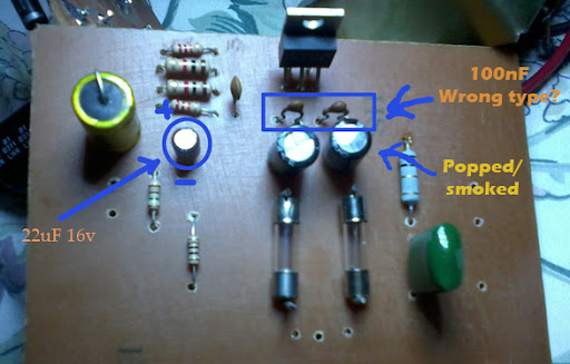
I tried using a 22uF 16v polarized cap like the one in this this post
http://www.diyaudio.com/forums/chip-amps/120616-lm1875-pcb-use-2.html#post1474466 and it's still intact.
The PBC layout was of Silicon Chip's. The 2.2uF NP cap is a bit big.
Before the cap smoked, I heard a loud hum on the speaker.
- Status
- Not open for further replies.
- Home
- Amplifiers
- Chip Amps
- LM1875 power supply