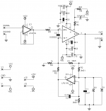
So for my next project, I'm trying to design my own board (and learning to use Eagle at the same time). As the title suggests, it's a LM3886 with servos for removing DC offset. I used the datasheet for the LM3886 and the non-inverting servo design from AN-1192. I have finished a first revision of the schematic design.
Notes:
- there is no input shunt resistor as I plan on using a passive attenuator
- all capacitor values are in uF
Let me know what you think!
Notes:
- there is no input shunt resistor as I plan on using a passive attenuator
- all capacitor values are in uF
Let me know what you think!
Attachments
peranders said:
D1 and D2 don't have to be schottkys, use regular diodes such as 1N4148,
Redshift187 said:
The app-note lists "low leakage" diodes for the servo. It might help if I actually understood what they do in this situation.
Hi D1,2 are protection for the integrator opamp. The chip amp outputs more than the opamp supplies (Vcc,Vee > +/-15 V), so it could turn on the LF411 substrate diode. Normally schottkys are prefered for this, but since R2 is so large to limit damage.
EDIT>signal diodes provide the lowest leakage, so are best here.
Hi,
the input impedance of the non-inverting 3886 is very high.
If you add that Zin resistor that Peranders talks about then that will define the input impedance of the amplifier. It will also supply the input offset current.
You do not need an input buffer to feed the Zin of this amp. Delete it.
Now, choose whether the attenuator needs a buffer to drive the interconnect.
Similarly decide if your source needs a buffer to drive their interconnects.
The 411 is excellent for the servo duty.
I suspect many opamps can provide a far better buffer than the 411. Change it.
Some low power transistors (I'm not calling them signal transistors deliberately) are even better when connected as diodes than diodes are with respect to leakage.
I think it was Jung that discussed particularly good transistors for this duty.
Finally,
a DC coupled amplifier with servo control of the output offset is great as long as all components are working properly.
Add a DC detect and output isolation to protect your speakers in case anything becomes faulty. Consider also adding an input mute activated by that same DC detect circuit.
Ok, starting on the input side. I've been reading more about servos, and it was recommended that servo amps have a low pass filter at the input so they don't oscillate at frequencies above the audio range. Does this sound like a good idea?
In the meantime I'll do more research about transistors for servo protection and DC detection circuitry.
In the meantime I'll do more research about transistors for servo protection and DC detection circuitry.
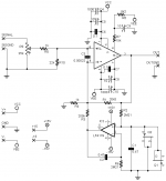
Ok, finally got around to updating this. Here is the amp circuit with the shunt resistor, input pot, input buffer removed, transistors for op-amp protection.
In order to keep the schematics easier to read, I'm making the DC detector and protection circuit a separate schematic.
In order to keep the schematics easier to read, I'm making the DC detector and protection circuit a separate schematic.
Attachments
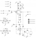
I have ordered boards very similar to the ones posted here (I thickened the power tracks, etc). I also ordered a speaker protection kit from eBay with the following schematic: http://s700.photobucket.com/albums/ww7/albert_tzeng/?action=view¤t=SP0419-1.png
My question is, it appears that C3, C3' and C5, C5' are pairs of electrolytics placed in opposite polarity. Would it be better for me to just use a bipolar electrolytic in place of C3 and C5 and use a wire in place of C3' and C5'?
My question is, it appears that C3, C3' and C5, C5' are pairs of electrolytics placed in opposite polarity. Would it be better for me to just use a bipolar electrolytic in place of C3 and C5 and use a wire in place of C3' and C5'?
This is not a good way because the servo can be extremely overdriven. It's better to have diodes between the inputs.aparatusonitus said:A right way to protect an J-Fet servo opamp input which I've learned recently from ilimzn")
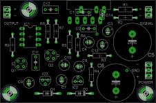
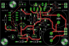
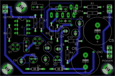
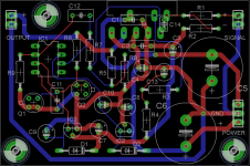
You have very thing power lines but it may not be a problem if the amp will go in light duty but for carrying 10 A peak it's not much.Redshift187 said:Complete layout:
My take with 95 um (2.5 oz.) copper
No!Redshift187 said:My question is, it appears that C3, C3' and C5, C5' are pairs of electrolytics placed in opposite polarity. Would it be better for me to just use a bipolar electrolytic in place of C3 and C5 and use a wire in place of C3' and C5'?
Yeah, I realized the power (and ground) tracks were too small, and made them much wider before I ordered the prototypes.
So, why is it a bad idea to replace those two electrolytics with a non-polar one? I've read that it's questionable to use two electrolytics reversed like that.
So, why is it a bad idea to replace those two electrolytics with a non-polar one? I've read that it's questionable to use two electrolytics reversed like that.
peranders said:
This is not a good way because the servo can be extremely overdriven. It's better to have diodes between the inputs.
We only need to ensure that the signal does not appear above or below servo opamp PSU voltage on his input. It is clear that will not appear at the + input which is earthed.
The caps aren't reversed in any way. This is a very normal application for such parts.Redshift187 said:Yeah, I realized the power (and ground) tracks were too small, and made them much wider before I ordered the prototypes.
So, why is it a bad idea to replace those two electrolytics with a non-polar one? I've read that it's questionable to use two electrolytics reversed like that.
- Status
- This old topic is closed. If you want to reopen this topic, contact a moderator using the "Report Post" button.
- Home
- Amplifiers
- Chip Amps
- LM3886 Servo Design