I´ve got a Audio System Twister F4-560, the previous owner wrote that it switched from red to green without any reason.
Missing screws and after disassembling the PCB I saw that somebody else worked on the Amp before.
The transformer had scratch marks at the primary side middle pins.
Q3 and Q4 were replaced.
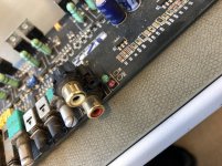
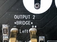
Output 2 "Bridge +" was "pushed" so that the solder connection broke at the top side.
The Case was pushed into the PCB which damaged the LED´s On and Protect.
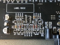
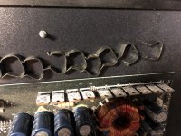
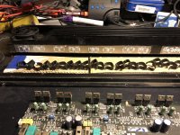
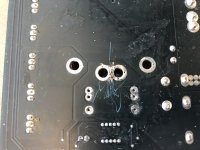
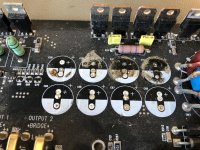
The biggest damage was caused by leaking electrolytic capacitors (C42, C69 Input capacistors; The link capacitors C38, C39, C40, C41, C65, C66, C67, C68) that burned/corroded the pads underneath. That caused most probably the green/red switcheroo. I didn´t switch it on with the damaged capacitors.
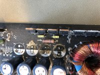
After desoldering and cleaning the PCB I coated the area around the contacts with a thin layer of lacquer for further protection.
I switched it on, only protect lit up. No life sign from the power supply.
I wasted a lot of time on the protection circuit, in the end I tried everything I could think of.
LM339 (U10) Quad comparator
Triggered the comparator outputs, Replaced the LM339, measured every SOT23 (2Gp - BC850C NPN, 4Gp - BC860C PNP) transistor out of circuit and checked the resistors on the paths.
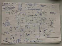
I used the schematic of the F2-190, backtraced as far as I could.
In the end I switched the Remote after the B+ on. That "solved" the problem. No Amp before had a problem with Remote and B+ on at the same time.
Should I look more into this?
The Amp switched on (Consumption 1,30A), it build rail-voltage up. (+/-36V)
Bias-Voltage at
DZ3: - 6,93V
DZ4: + 6,99V
Pre-Amp voltage -18,50V and +18,53V at the transistors Q75 and Q76.
Missing screws and after disassembling the PCB I saw that somebody else worked on the Amp before.
The transformer had scratch marks at the primary side middle pins.
Q3 and Q4 were replaced.
Output 2 "Bridge +" was "pushed" so that the solder connection broke at the top side.
The Case was pushed into the PCB which damaged the LED´s On and Protect.
The biggest damage was caused by leaking electrolytic capacitors (C42, C69 Input capacistors; The link capacitors C38, C39, C40, C41, C65, C66, C67, C68) that burned/corroded the pads underneath. That caused most probably the green/red switcheroo. I didn´t switch it on with the damaged capacitors.
After desoldering and cleaning the PCB I coated the area around the contacts with a thin layer of lacquer for further protection.
I switched it on, only protect lit up. No life sign from the power supply.
I wasted a lot of time on the protection circuit, in the end I tried everything I could think of.
LM339 (U10) Quad comparator
Triggered the comparator outputs, Replaced the LM339, measured every SOT23 (2Gp - BC850C NPN, 4Gp - BC860C PNP) transistor out of circuit and checked the resistors on the paths.
I used the schematic of the F2-190, backtraced as far as I could.
In the end I switched the Remote after the B+ on. That "solved" the problem. No Amp before had a problem with Remote and B+ on at the same time.
Should I look more into this?
The Amp switched on (Consumption 1,30A), it build rail-voltage up. (+/-36V)
Bias-Voltage at
DZ3: - 6,93V
DZ4: + 6,99V
Pre-Amp voltage -18,50V and +18,53V at the transistors Q75 and Q76.
Attachments
-
 IMG_8707.jpg905.4 KB · Views: 113
 -
 IMG_8709.jpg1 MB · Views: 119
 -
 IMG_8746.jpg1,020 KB · Views: 129
 -
 IMG_8760.jpg759.6 KB · Views: 104
 -
 IMG_8764.jpg1,019.3 KB · Views: 173
 -
 IMG_8765.jpg942.5 KB · Views: 89
 -
 IMG_8768.jpg1 MB · Views: 83
 -
 IMG_8786.jpg986.2 KB · Views: 79
 -
 IMG_8784.jpg1 MB · Views: 91
 -
 IMG_8839.jpg666.3 KB · Views: 94
This is good reminder for those working on GT trading amps. I didn't see many (any?) Twister amps here but Boston and Polk(?) had amps that used similar circuits and wouldn't turn on when remote and B+ were applied at the same time.
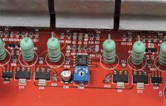
If the boards don't have GT Trading on the board, the layout with the op-amp very near the outputs and the bias pot is a good way to identify the GT Trading amps. This is for a Boston amp.
If the boards don't have GT Trading on the board, the layout with the op-amp very near the outputs and the bias pot is a good way to identify the GT Trading amps. This is for a Boston amp.
Attachments
Audio System Amps are build pretty similar in shape and design of the channels and drive circuits.
I used this schematic as a reference. Picture 2 is transcribed to the notation of the F4-560
AUDIO SYSTEM F2-190 Service Manual download, schematics, eeprom, repair info for electronics experts
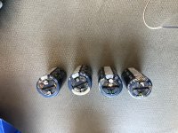
Power Supply FET´s (Q17, Q18, Q19, Q20, Q21, Q22)
Marking: 75343P = STP60N55F3 (80A, 55V, 9mOhm) --> Discontinued
STP75N75 (75A, 55A, 9mOhm)?
AUIRF3305 (140A, 55V, 8mOhm)?
Rectifiers (D1, D2, D3, D4)
China STPR15
Output-Stage (Q1, Q2, Q3, Q4, Q5, Q6, Q7, Q8, Q9, Q10, Q11, Q12, Q13, Q14, Q15, Q16)
Left side of channel (N-Channel)
IRF540A (100V, 28A, 52mOhm) --> Discontinued
FQP33N10 (100V, 33A, 52mOhm)
Right side of channel (P-Channel)
SFP9540 (100V, 17A, 0,2Ohm) --> Discontinued
Infineon IRF9540NPBF (100V, 23A, 0,117Ohm)
Vishay IRF9540PBF-BE3
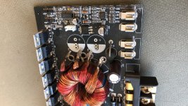
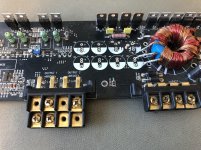
Transformer (Measured with Agilent U1733C)
Primary From top to bottom - Red, Yellow, Red, Yellow
Z= 0,3515 Ohm
L= 56,10 uH
C= 453,1 uF
R= 0,0316 Ohm
Z= 0,3470 Ohm
L= 54,91 uH
C= 457,7 uF
R=0,0327 Ohm
Secondary From top to bottom - Red, Yellow, Red, Yellow
Z= 2,927 Ohm
L= 464,3 uH
C= 54,75 uF
R= 0,0473 Ohm
Z= 2,882 Ohm
L= 458,0 uH
C= 55,45 uF
R= 0,0462 Ohm
Potentiometer
TRM1: 2,256kOhm
TRM2: 2,531kOhm
TRM3: 2,638kOhm
TRM4: 2,779kOhm
Fan 1/2: TOP MOTOR DF1206SH (DC12V, 0,20A, 2,4W)
I used this schematic as a reference. Picture 2 is transcribed to the notation of the F4-560
AUDIO SYSTEM F2-190 Service Manual download, schematics, eeprom, repair info for electronics experts
Power Supply FET´s (Q17, Q18, Q19, Q20, Q21, Q22)
Marking: 75343P = STP60N55F3 (80A, 55V, 9mOhm) --> Discontinued
STP75N75 (75A, 55A, 9mOhm)?
AUIRF3305 (140A, 55V, 8mOhm)?
Rectifiers (D1, D2, D3, D4)
China STPR15
Output-Stage (Q1, Q2, Q3, Q4, Q5, Q6, Q7, Q8, Q9, Q10, Q11, Q12, Q13, Q14, Q15, Q16)
Left side of channel (N-Channel)
IRF540A (100V, 28A, 52mOhm) --> Discontinued
FQP33N10 (100V, 33A, 52mOhm)
Right side of channel (P-Channel)
SFP9540 (100V, 17A, 0,2Ohm) --> Discontinued
Infineon IRF9540NPBF (100V, 23A, 0,117Ohm)
Vishay IRF9540PBF-BE3
Transformer (Measured with Agilent U1733C)
Primary From top to bottom - Red, Yellow, Red, Yellow
Z= 0,3515 Ohm
L= 56,10 uH
C= 453,1 uF
R= 0,0316 Ohm
Z= 0,3470 Ohm
L= 54,91 uH
C= 457,7 uF
R=0,0327 Ohm
Secondary From top to bottom - Red, Yellow, Red, Yellow
Z= 2,927 Ohm
L= 464,3 uH
C= 54,75 uF
R= 0,0473 Ohm
Z= 2,882 Ohm
L= 458,0 uH
C= 55,45 uF
R= 0,0462 Ohm
Potentiometer
TRM1: 2,256kOhm
TRM2: 2,531kOhm
TRM3: 2,638kOhm
TRM4: 2,779kOhm
Fan 1/2: TOP MOTOR DF1206SH (DC12V, 0,20A, 2,4W)