Thanks for your reply. I will check all the voltages tomorrow, however yesterday I noted that there is no voltage on pin 12 of the TL494. I tried to follow the track of the supply of the IC, and I noticed that there is a transistor (close to 2 diodes) that has 12V on the base and emitter (If I am not mistaken) but the collector has no voltage on it. I checked the transistor with the DMM on diode check and I noticed that it is not faulty.
Hi,
Sorry my mistake. I just noticed that the remote wire was cut and that is why the amplifier was not powering on. Still the amplifier has no audio out (there was a short on one of the output speakers, in fact the connector has melted). I disconnected the AD2K module and noticed that there is a transistor (part number 2D) that is giving 0.68V between Base and Collector and 1.46V between Base and Emitter. Probably the fault of no output is coming from there. Do you agree? I will try to find an equivalent and replace and will reply back. In the mean time if you have any hints on this fault, please contact me via this forum. Thanks and happy festive season.
Sorry my mistake. I just noticed that the remote wire was cut and that is why the amplifier was not powering on. Still the amplifier has no audio out (there was a short on one of the output speakers, in fact the connector has melted). I disconnected the AD2K module and noticed that there is a transistor (part number 2D) that is giving 0.68V between Base and Collector and 1.46V between Base and Emitter. Probably the fault of no output is coming from there. Do you agree? I will try to find an equivalent and replace and will reply back. In the mean time if you have any hints on this fault, please contact me via this forum. Thanks and happy festive season.
Yes re the PSU, it was due to a broken wire between the remote connection and the 12V supply. That is why I have not posted anything on the PSU chip, since that is not the main fault. The main fault is basically that there is no audio output. I replaced the transistor with one I had (2n3906) I know that this transistor is not a direct equivalent, but I wanted to test the amp. It still gave no output. Tomorrow I will try to use the scope to check the signals on the opamps. Re the circuit diagram for the audio part, I have found it in previous posts. I will try to do some work on it tomorrow and I will reply back with any results I have. Thanks.
Same Problem again
Hi,
This amplifier is giving me trouble again. I noticed that when I switch on with the remote wire connected to supply, the power supply of the amplifier switches on fine, but when I apply the remote voltage after switching on, the red LED remains on. The voltages of the TL494C are as follows:
Pin 1: 0.98V
Pin 2: 2.44V
Pin 3: 4.62V
Pin 4: 0V
Pin 5: 1.42V
Pin 6: 3.61V
Pin 7: 0V
Pin 8: 13.78V
Pin 9: 0V
Pin 10: 0V
Pin 11: 13.78V
Pin 12: 12.74V
Pin 13: 4.92V
Pin 14: 4.92V
Pin 15: 4.92V
Pin 16: 13.78V
Thanks
If power is applied to the amplifier and then the remote wire is connected to supply, the amplifier will not power up (red LED remains on and does not switch to the blue LED). If I connect the remote to the supply then I apply power (on the +ve input) it powers on properly and there is sound output. If I disconnect the remote wire and then connect it again, then the LED remains RED and no audio is heard.
Hi,
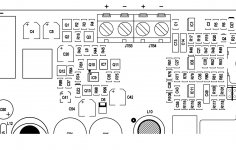
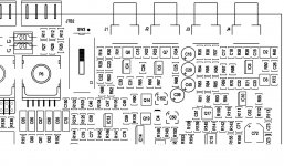
that protection - pin 16 high - is triggered for two reasons: dc output or gnd rca faulty. It is better to remove the two protections, one at a time, and see which one causes the problem:
DC-OUT = remove R4
GND RCA = remove Q17
that protection - pin 16 high - is triggered for two reasons: dc output or gnd rca faulty. It is better to remove the two protections, one at a time, and see which one causes the problem:
DC-OUT = remove R4
GND RCA = remove Q17
Attachments
Hi,
I tried to remove Q17 and R4 but the fault remained the same. I noticed that if I bypass R197 for a few seconds, the power supply will turn on. I checked the resistor and it is giving the correct value. I also checked and replaced C89 but the fault remains the same. Please note that if I switch the supply of the amplifier with the remote connected, it will operate normally.
Thanks for your help.
Sorry for the late reply. I found the resistor out of tolerance and I replaced it and to be on the safe side I replaced the capacitor too, but the fault still remained there. I really don't know why if R197 is bypassed for a few seconds, the amp will power on (blue LED turns ON and Red LED turns OFF)
The remote is being applied within a few seconds. The thing is that if the remote is applied together with B+ the BLUE LED turns on and the amp is OK. If the remote is applied even 2 seconds later, the RED LED remains ON.
The voltage on Pin 16 is:
11.74V with remote voltage applied
0V without remote voltage
The voltage on Pin 15 is:
4.92V with remote voltage applied
0V without remote voltage
Thanks
The voltage on Pin 16 is:
11.74V with remote voltage applied
0V without remote voltage
The voltage on Pin 15 is:
4.92V with remote voltage applied
0V without remote voltage
Thanks
Hi, Without R195, the RED LED will not turn ON, but the AMP starts normally when remote voltage applied. On the speakers there is just 0.03VDC when the AMP is not loaded and OFF and 0VDC when the AMP is ON.
The value of R195 was 100r and I replaced it with same value when it was out of tollerance.
Thanks
The value of R195 was 100r and I replaced it with same value when it was out of tollerance.
Thanks
My opinion there can be two situations.
situation A:
1. Do not connect REM for 5 min
2. Connect REM
3. AMP turns-on normally, no red led
situation B:
1.With AMP on normally, remove REM
2. After a few seconds connect REM
3. AMP protection, red led
If the situation is B, then it is NORMAL because you have to wait one or two minute after
turn-off amplifier, before turn-on it again.
Some amps do this because may be some 'spk bump' problems or stuff like that when
you turn-off then turn-on amp fast.
Monitor pin 12 of the 494 with your scope.
Have B+ and ground connected, then apply remote. How long of a delay, after applying remote is there for pin 12 to receive 12v?
Monitored pin 12 and the voltage is going to 10.7V immediately and remains like that (i monitored for 20 seconds)
- Status
- This old topic is closed. If you want to reopen this topic, contact a moderator using the "Report Post" button.
- Home
- General Interest
- Car Audio
- Amplifier SR1DK