I’m working on an American Bass VFL 110.1 (very similar to AudioQ amps) that had a damaged output section. Many of the output mosfets were shorted. I replaced all of them, high side and low side drive.
This amp has the 11 pin driver card for the output section. I also replaced the TL072s on the driver board. The amp boots up and pulls normal amps (about 2 amps or less) after the initial spike when it first boots up. The relay clicks in and the amp immediately protects and turns the relay back off.
I do see a DC voltage across the speaker terminals it climbs quickly to about 10 volts before the amp protects.
I am wondering what could be causing this behavior as all of the output mosfets are new.
David
I didn’t get much time to work on this amp today.
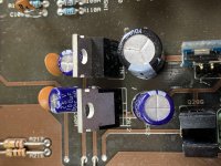
Yes, the amp is driving DC to the output inductor and if I turn the voltage down from 14 volts to 12 volts I can watch the DC voltage on the inductor and speaker terminals slowly creep up to just over 3 volts DC before the protection circuit disengages the relay and the power supply shuts down.
That’s about as far as I got with it.
David
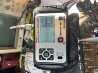
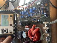
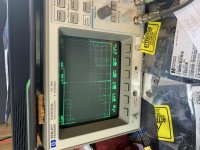
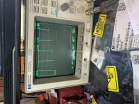
This the drive signal on the high side and low side drive. It’s hard to tell from pictures but the drive signal isn’t stable. It fluctuates between 190 and 230 kHz at 0.5 volts on the high side and low side FETs.
I am using a battery powered Oscope because I can’t get the drive signal to show up clearly on my mains powered scope. I’m not sure why. But I digress.
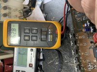
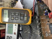
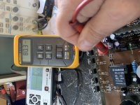
High side rail voltage is approx 59 volts and low side rail voltage is approx 62 volts.
Photo one is high side drive and photo two is low side drive.
David
I am using a battery powered Oscope because I can’t get the drive signal to show up clearly on my mains powered scope. I’m not sure why. But I digress.
High side rail voltage is approx 59 volts and low side rail voltage is approx 62 volts.
Photo one is high side drive and photo two is low side drive.
David
Attachments
When I try to view the wave form on my mains powered scope all I see is a bunch of scattered dots. When I zoom in with time division I can see some resemblance of the wave form but it is still just a bunch of dots. No defined lines. I am grounding the probe to the negative terminal of the amplifier.
I am measuring the rail voltage with my fluke 12 grounded to the negative terminal of the amplifier.
David
I am measuring the rail voltage with my fluke 12 grounded to the negative terminal of the amplifier.
David
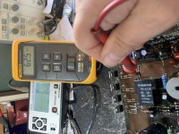
No matter which leg I probe, if the is a drive wave there then I get that image on the scope. If I get on a leg with DC voltage the the trace deflects off the screen.
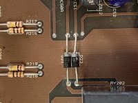
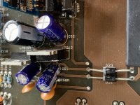
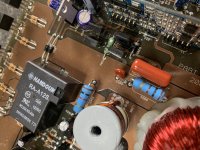
On a side note. I notice that R256 (measures 100 ohm) gets really hot and R262 (measures 1k ohm) is staying stone cold. Is that normal?
David.
On a side note. I notice that R256 (measures 100 ohm) gets really hot and R262 (measures 1k ohm) is staying stone cold. Is that normal?
David.
Attachments
- Status
- This old topic is closed. If you want to reopen this topic, contact a moderator using the "Report Post" button.
- Home
- General Interest
- Car Audio
- American Bass VFL 110.1 protection after relay