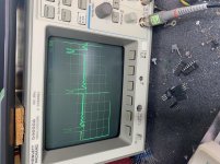
That's the low side but it's a much better waveform. It looks like it's either being modulated by an audio signal of the trigger level needs to be adjusted.
Trigger is set to auto and there is no audio being driven into the amp. Even with noise rejection turned on it still looks the same.
The drive signal on the gates of the other side of the FETs looks the same as the tab on the other side.
So I have uneven rail voltage, a noisy looking drive signal, about 3 volts DC on the speaker terminals, and R256 heating up.
Should I take out back and put it out of it’s misery or do I need to take another look at the driver board or possibly something with the 7812 or 7815 regulators, or something I haven’t thought about?
I don't see any markings on the pot in the manual. 0v isn't necessarily the right setting. Sometimes you have to work with it quite a bit to get it to trigger properly.
The trigger level doesn’t clean up the drive signal in any of the modes other than make it worse if you go too far in one direction or the other.
Adjusting the hold off to about 4.6us does clean it up a little bit but not much.
Adjusting the hold off to about 4.6us does clean it up a little bit but not much.
Attachments
I pulled the output mosfets from this amp and it no longer goes into protection. I’m still reading 1.5 vdc at the speaker terminals.
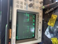
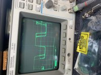
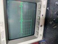
This is the drive signal on the low side and high drives. I was wondering if this looks normal before I go any further with this. The drive signal looks the same at the pads of the mosfets as it does coming out of the driver board measured before it reaches the motherboard.
Probe is 1x, scope is set to 5v/div, 5us
Thanks for your input.
David
Attachments
I would revisit the drive card (do you get excessive hot spots when powered on), check the pull-down and gate resistors and double-check the output transistors. Not many ways for DC to get to the output if the output transistors are being driven correctly.
You initially stated that the amp had DC on it's output but the waveforms you've posted show nothing that would produce significant DC offset and the amp is remaining on long enough for you to get the images of the waveforms. What has changed?
All I did was remove the output mosfets.
Then I powered up the amp to look at the wave forms and that’s the pictures I posted today.
As for yesterday...
When I was taking the scope images before I removed the outputs all I did was lower the voltage to the amp from 14 volts to 10 volts. The DC to the output would slowly rise to 3 volts before the protection circuit kicked in. That would usually take about a minute. At 14 volts the DC would rise in a matter of seconds.
David
- Status
- Not open for further replies.
- Home
- General Interest
- Car Audio
- American Bass VFL 110.1 protection after relay