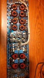
This amps uses fda24n40f outputs.I don't have enough at the moment and want to confirm drive signal.Can irf640's be used? They can handle the voltage just not sure about the RDS on being a factor.
Also,can one output be installed in each bank for testing instead of installing all of them?
To check high side drive,do the low side outputs need installed?And do I have to have at least one output in every bank or can I install one to check one bank at a time since there is 4 ir21844's?
Also,can one output be installed in each bank for testing instead of installing all of them?
To check high side drive,do the low side outputs need installed?And do I have to have at least one output in every bank or can I install one to check one bank at a time since there is 4 ir21844's?
Now I understand.Thanks.
Anyhow,what (if any) is the minimum number of outputs I can install to check drive signal?
Can I install just one high for one ir21844?Or do I have to have a low side in as well?Or intact in single one?
Just a little nervous because the chips and outputs are expensive and I have limited amount until my order shows.
Testing with fewer than the full load of FETs isn't definitive. You may as well test without FETs with a low frequency audio signal. I'm not familiar with this amp but if there is no high-side drive supply voltage, you may have to provide one if there is no high-side drive signal. A 9v battery works. You'll also have to ground the output filter inductor terminal that's connected to the FETs. All of this is with NO outputs installed.
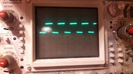
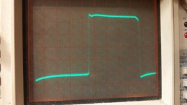
I think I understand you.So ground all 4 filter inductors to amplifier ground terminal.Run a 50hz tone into the amp.Just so you know,the amp had good low side signal.The high side was swinging rail to rail on the gate and looked terrible on one side.The other side of the amp had no high side drive.
Replaced all four ir21844s's and trying to test now.
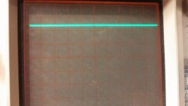
If I power the amp up slowly it does not start to produce high side drive and its making me nervous.
Besides the inductor grounding and 50hz tone.How do I provide high wide drive with 9volt battery exactly?
Replaced all four ir21844s's and trying to test now.
If I power the amp up slowly it does not start to produce high side drive and its making me nervous.
Besides the inductor grounding and 50hz tone.How do I provide high wide drive with 9volt battery exactly?
The high-side drive will not swing rail-rail without output transistors. To clarify, it doesn't actually swing rail to rail. It only swings about 10v but it's referenced to the high-side source leg which does swing rail to rail, it appears that the high-side drive swings rail to rail when the amp is in operation.
If you see rail-rail swing with no outputs in the circuit, there is a problem.
You connect the 9v battery across the high-side capacitor. Look up the datasheet. The terminal of the cap connected to the VS terminal is the negative battery connection. The VB is the positive battery connection. Confirm that you have no voltage across those points before connecting the battery. I'd suggest inserting a 1 amp fuse to protect the battery in case there is a problem.
Remember NO output transistors installed.
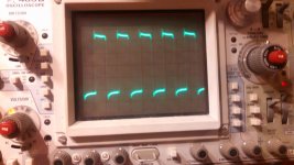
The actual drive signal can't be more than about 20v, otherwise it would destroy the FETs. The high-side rides on the rail-rail square wave so it appears to swing rail to rail but it's no more than a 10v (approximately) signal.
The drive signals that drive from both rails are for amps that use N and P-channel FETs (type 1 page for waveforms). This amp uses all N-channel FETs (type 4 page for waveforms).
The drive signals that drive from both rails are for amps that use N and P-channel FETs (type 1 page for waveforms). This amp uses all N-channel FETs (type 4 page for waveforms).
- Status
- This old topic is closed. If you want to reopen this topic, contact a moderator using the "Report Post" button.
- Home
- General Interest
- Car Audio
- Cactus 5K outputs(clone)