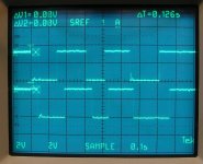
This is from a JVC but the function is likely the same. It appears that the volume is stepped when one transitions from high to low then the other transitions the same. They can begin at ground or at 5v. The up/down is determined by which one transitions first. The two images show volume adjusted one way and volume adjusted the other way. I don't remember which is which.
Attachments

You really do need to get a scope onto the encoder. I have bought 3 batches off eBay and now have three different types of encoder.
One is Gray code, one kind of binary one the third is quite silly but works. The micro I use these on now has three sets of code in the isr that handles this, and jumpers so I can tell it what to look for.
The message being: just shorting wires on an encoder input won't work. Pumping a square wave in might do something, but odds are it will not be useful.
You can definitely develop an emulator for it. Easiest way would be using a micro controller. That way you could mix in the second rotary encoder by reading that in the micro controller, combining the resultant commands and driving one set of outputs to the head unit.
Sounds like a lot if work to save moving your hand one foot from he steering wheel.
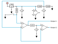
The circuit below works in the JVC head unit. The switch could be replaced by a 555 timer output set for 2-3Hz. The outputs have to be reversed to step up or down. This could be done by two double-pole relays with opposite connections. One would be engaged to step up. The other to step down.
If you do this, you will probably have to remove the encoder. The encoder can stop open or shorted. If it is on a shorted location, the circuit cannot drive the signals to the processor.
The circuit requires an op-amp that can accept inputs at ground. Many audio op-amps cannot do that. The circuit works with an LM358 and a TLC2272. The 2272 swings rail to rail so it provides a bit better pulse but either should work.
Attachments
Sounds like a lot if work to save moving your hand one foot from he steering wheel.
I'm starting to think so. I just don't like to give up on an idea I have.
Also, there isn't any way around having the encoder and building that circuit to emulate the encoder? Maybe with the use of diodes to prevent the current from going back to the encoder?
I also have tried using a 555 timer in astable mode but at 65Hz (its just what I had laying around) and it didnt work for changing the volume. While on, it disabled the use of the encoder, then when off the encoder worked again.
Scratch that about the diode, (still early here) How about adding a relay or something that will switch patch from the encoder to the simulator circuit when activated?
Which circuit are you referring to? There have been several suggestions. The circuit I posted isn't a logic circuit.
The last diagram. It has resistors, capacitors, voltage regulator, switching diode. Aren't the last 3 components gates? Or are those op amps?
Simple op-amps. Nothing is critical but I'd use the TLC2272 for the op-amp because it swings from rail to rail.
Do your steering wheel controls have straight, dedicated wires for up and down that read 0 ohms to ground (or to the common wire) when the buttons are pressed?
That's not common on many of the newer cars that use the data-bus systems.
That's not common on many of the newer cars that use the data-bus systems.
Yes, it used to have a resistive board that had 5 buttons for the stock radio but all I use is the 2 for volume, so I made a new board to utilize the 2 buttons and the 3 wires that go through the clockspring.
Thank you Perry Babin! It worked great! Now I just need to make a PCB with these components and add a relay for the output. You are a life saver!
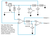
Would this work for the volume control push buttons? I'm not 100% sure the diode next to the switch will allow the up button to ground pin 3 only and not the DPDT. Then the down button would ground pin 3 also and the coil for the DPDT relay to reverse the output.
Attachments

That should work. Remember, you either have to have the encoder on an open position or disconnected.

Have you tried this with the relay yet? I'd be concerned that the relay could not engage quickly enough and the first pulse might be missed.
- Status
- Not open for further replies.
- Home
- General Interest
- Car Audio
- Volume control with rotary encoder and pushbuttons?