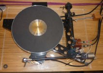
Hi all. I have been planning a few diy upgrades for my Sondek for a while so I thought I should share the plans and see what you all thought. I'm still in the design phase so there is plenty of opportunity to refine it. The updates will be done in a month or two. I have a few parts to make first and also waiting for delivery of a motor from Maxon.
The turntable is presently a fairly basic spec unit. I fitted a new AC motor and made an Armageddon clone drive for it earlier in the year. Also made a prototype aluminium sub chassis and re-wired the arm, which is a REGA RB202. Sound quality is ok but it clearly has a long way to go. There is some vibration from the motor so must be affecting the performance a lot.
The next round of upgrades have been in design for around 6-months. I stripped and measured the turntable an re-created it in CAD (Creo). I have used this to design new parts and assess them using Creo Simulate FEA. When I looked at the standard LP12 design I was surprised how basic it is and there are several poor features and a lack of stiffness in the structure and sub-chassis. Upgrades from Linn are so very expensive and just fix their own crap design features! My plan has been to match or improve some of those upgrades for a fraction of the cost.
I will put a few more posts on to show details. There are 4 main upgrades; new tonearm, subchassis, fix top plate resonance, and add a decent DC motor with closed loop voltage control. I'm hoping these will give good performance and get me rocking with the old vinyl collection.")
Picture below shows one of the problem areas that I have been looking at and assessing loads of design options - subchassis. The standard pressed steel subchassis looks poor and the analysis confirms this. It weighs around 1.1kgs and there is a further 3.7kgs of weight on it from the platter and tonearm. This weight makes is resonate at a low frequency. There is a first order resonance of just 52Hz. This cant be very good for bass performance!
The turntable is presently a fairly basic spec unit. I fitted a new AC motor and made an Armageddon clone drive for it earlier in the year. Also made a prototype aluminium sub chassis and re-wired the arm, which is a REGA RB202. Sound quality is ok but it clearly has a long way to go. There is some vibration from the motor so must be affecting the performance a lot.
The next round of upgrades have been in design for around 6-months. I stripped and measured the turntable an re-created it in CAD (Creo). I have used this to design new parts and assess them using Creo Simulate FEA. When I looked at the standard LP12 design I was surprised how basic it is and there are several poor features and a lack of stiffness in the structure and sub-chassis. Upgrades from Linn are so very expensive and just fix their own crap design features! My plan has been to match or improve some of those upgrades for a fraction of the cost.
I will put a few more posts on to show details. There are 4 main upgrades; new tonearm, subchassis, fix top plate resonance, and add a decent DC motor with closed loop voltage control. I'm hoping these will give good performance and get me rocking with the old vinyl collection.
Picture below shows one of the problem areas that I have been looking at and assessing loads of design options - subchassis. The standard pressed steel subchassis looks poor and the analysis confirms this. It weighs around 1.1kgs and there is a further 3.7kgs of weight on it from the platter and tonearm. This weight makes is resonate at a low frequency. There is a first order resonance of just 52Hz. This cant be very good for bass performance!
Attachments
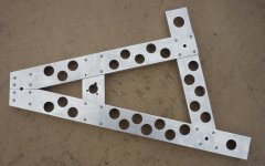
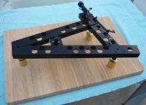
Can I suggest a less expensive and better upgrade path for your "fairly basic spec " LP12 is to use some of its parts to turn it into a 'SkeletaLinn' - as I have done.
A couple of pics are attached; if this is of interest, by all means PM me.
Several advantageous features of the 'SkeletaLinn' are:
1. the arms are rigidly attached to the bearing/platter - providing the level of detail retrieval given by the Keel.
2. the motors are off-board (no vibration problems).
3. the motor controller I have ('Number9') is able to drive 2 motors - diametrically opposed - and apply a phase difference between their power cycles (so they don't both 'drive' at the same time). Using 2 motors:
* provides double the torque of just one motor - which you can hear delivers improved SQ, and
* removes the LP12 problem of the belt pulling the bearing to one side.
The pics are of v2 of the chassis (which is slightly different to v1); v3 is in the process of being CNC'd - this will be a chassis milled from a slab of Delrin ... rather than using aluminium C-section bolted together.
Regards,
Andy
Attachments
Last edited:
Wow that's radical! Love it. Some out of the box thinking has gone into your version.
I have thought about a double motor, or adding an idler pulley to balance the loads on the platter. I know the single motor/pulley does pull the sub chassis from its 'free' position a little. This must influence the behaviour of the suspension. I will see if that could work in my design.
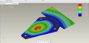
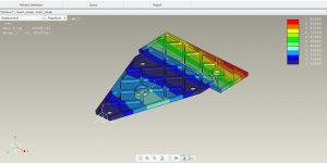
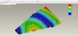
I know that getting a good connection between the platter and arm is key so I have been looking at that area carefully. The Keel seems to be the best off the shelf upgrade option so I looked at that design, did a CAD model of it and some FEA. Its stiffer than the pressed steel version but I was surprised its not as good as I expected. It has a resonance of 91Hz - see image below. The FEA setup I did has the sub chassis fixed vertically at the 3x springs and the weight of the tonearm and platter added. Its therefore hanging from the springs which are effectively fixed points in the simulation.
I have thought about a double motor, or adding an idler pulley to balance the loads on the platter. I know the single motor/pulley does pull the sub chassis from its 'free' position a little. This must influence the behaviour of the suspension. I will see if that could work in my design.
I know that getting a good connection between the platter and arm is key so I have been looking at that area carefully. The Keel seems to be the best off the shelf upgrade option so I looked at that design, did a CAD model of it and some FEA. Its stiffer than the pressed steel version but I was surprised its not as good as I expected. It has a resonance of 91Hz - see image below. The FEA setup I did has the sub chassis fixed vertically at the 3x springs and the weight of the tonearm and platter added. Its therefore hanging from the springs which are effectively fixed points in the simulation.
Attachments
Thank you, Dean. 
There is a problem that I think you can't get away from, using Linn geometry (to fit in with a standard top-plate & plinth) - this is ... that there is not equal weight distribution across the 3 springs. (The 'arm spring' is always wound up tighter than the others.)
My v2 was more even than v1 - but v3 (currently under construction) should have almost equal weight distribution across the 3 springs. (It's a matter of moving the bearing (/platter) around, relative to the arm positions; I developed a weight model in Excel and the magic of the CAD program delivered the weight - and the CoG - of the chassis itself.)
Andy
There is a problem that I think you can't get away from, using Linn geometry (to fit in with a standard top-plate & plinth) - this is ... that there is not equal weight distribution across the 3 springs. (The 'arm spring' is always wound up tighter than the others.)
My v2 was more even than v1 - but v3 (currently under construction) should have almost equal weight distribution across the 3 springs.
(It's a matter of moving the bearing (/platter) around, relative to the arm positions; I developed a weight model in Excel and the magic of the CAD program delivered the weight - and the CoG - of the chassis itself.)Andy
That's a good point Andy but it is possible to balance it all up with the top plate. I just needs another hole drilling nearer to the tonearm. I get a weight distribution of 1.4, 1.7 and 2.2 kgs for left, front and rear springs as standard. It seems a bad distribution and all the spring will be trying to resonate at slightly different frequencies - between 4.5 to 5.2 Hz. I have moved the rear spring nearer to the tonearm by around 20mm and expect the forces will all within 1%. I expect this will make the subchassis bounce more evenly - at 4.8Hz
I measured the standard springs and they don't seem to be perfectly suited to the job. They are conical and I notice the large diameter end starts to coil bind after 11mm compression. Doesn't seem a great position to be in. The rear spring needs around 17mm compression to support 2.2kgs. Im my design I expect all will need 15mm of compression. I have been looking at alternatives options for springs but don't have anything in the plan yet. Have you used the standard springs?
I measured the standard springs and they don't seem to be perfectly suited to the job. They are conical and I notice the large diameter end starts to coil bind after 11mm compression. Doesn't seem a great position to be in. The rear spring needs around 17mm compression to support 2.2kgs. Im my design I expect all will need 15mm of compression. I have been looking at alternatives options for springs but don't have anything in the plan yet. Have you used the standard springs?
I measured the standard springs and they don't seem to be perfectly suited to the job. They are conical and I notice the large diameter end starts to coil bind after 11mm compression.
Yes, I have observed that too.
I asked Ivor why he used conical springs, when he came to Melbourne, to deliver a talk to the Linn fan bois, about 5 years ago - and he said there was a good reason ... something about sideways stability (which didn't make any sense to me)?Have you used the standard springs?
In v1 of my SkeletaLinn chassis, I had the bearing point too close to the LH spring - so I needed to have made up some springs that were about 30% stiffer than the standard Linn springs. So v1 has this stiffer spring on the LH side.
v2 - my current TT - reduced the weight on the LH spring by moving it 50mm away from the bearing, to the left ... so uses standard Linn springs. However (because I didn't get the weight distribution correct), the LH spring is still more compressed than the others.
v3 of the chassis - in construction - should have pretty much equal weight on all 3 springs ... so the extra compression which the LH spring experiences now, should be removed. But I will be moving to "mag-lev" springs, designed by the guy who developed the 'Number9' motor controller - which should improve the spring performance.
Andy
Hi deano1712
Do your own thing, make a new turntable using all your ideas, In the meantime have a decent LP12 to listen to some nice records and use it as a reference for your own build.
regards, klaus
Klaus; good idea but making a turntable from scratch is maybe a future option for me. I think I would spend years designing it if I tried. Will see how this project goes first. I always wanted a LP12 as a boy but it was beyond reach, then kids etc etc.
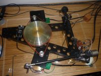
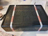
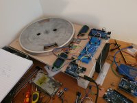
Got a delivery from Maxon today so that's good, a little earlier than they promised, and no VAT to pay thankfully. I went for a DCX 24v. I have made a test rig to get it working and optimise the drive circuit and software. Plan is to control it via an Arduino DUE. This has a pure dc output 12-bit signal @ 3.3v. I don't know yet what the motor is going to need as a nominal voltage for 45 and 33rpm. Probably over 3.3v. Im not great with electronics so if anyone can help with ideas for a drive circuit that would be good. I also need a pulley.
Attachments
Last edited:
Yes, I have observed that too.
Lateral stability is an issue. I've seen a couple different takes on addressing it, but not by Linn.
jeff
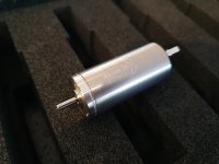
Which Maxon is that?
The motor? Its a DCX. 22mm 24 volt, precious metal bushes, sintered sleeve bearings
maxon - Online Shop | maxon group
Maxon website includes this article where they say its super quiet.
The perfect record player | maxon group
Last edited:
.. I always wanted a LP12 as a boy but it was beyond reach ....
Hi deano1712,
So did I. Now I have a decent LP12 on my shelf and a prototype using a DUAL-DirectDrive and a simple Bamboo-Plate with a nice Thorens-ToneArm that tells me, how easy building a nice turntable can be.
Next step will be a real diy-turntable, sometime.
About your maxon-motor.
If you look at the specs of the motor there is a ratio U/min versus voltage. The rotational speed depends on the ratio of the diameter of your pulley and your platter. Now you can calculate either rotational speed of the motor or diameter of the pulley, next step is calculating the voltage you need.
The easy way is using a Linn-pulley and a linn-subplatter, the rotational speed of the premotec motor is 250 per minute, as far as I know.
Good luck with your project !
Regards, Klaus
The test rig I made has a single magnet on the platter with a hall sensor. Im using the Arduino to monitor the speed via interrupt and its adjusts the speed incrementing the volts out proportional to the speed error. I think the switch on the LP12 is momentary action so I have the program checking state of that via a second interrupt routine and it selects 33rpm on one button press, 45 for 2 and the 3rd button press switches it off. I have had this running with a cheap Chinese motor with an UNO outputting PWM and it seems to work ok. The UNO outputs PWM and only to 8-bit resolution. This is giving audible noise so I now have a DUE to try which has a true DC out via a DAC and can be set to 12-bit. I'm hoping this will get good enough speed resolution.
An alternative solution to changing the pulley would be to drive the outer rim of the platter. But obviously, you'll need a larger diameter belt!
Good Luck!
The motor will still be going very slowly circa 300 rpm. The motor spec says it rotates at 211rpm per volt. Driving it at 1 to 2 volts seems low? I want to try a pulley 10mm or less. Still don't see anything I can buy for this. I do have a lathe so may end up making a pulley myself will have to see how well that goes.
The sub-chassis on the LP12 is a key part of the turntable and I have been giving the design of it a lot of thought and analysis. There are clearly many possible upgrades in the marketplace for this. The Linn Keel seems to have the best reputation so I have used that as benchmark for my design. Its clearly a lot stiffer than the original pressed steel version and there is direct connection between the bearing and tonearm. The Keel costs around 2700GBP to buy which is unbelievable for a piece of aluminium weighing 1.1kgs! I considering buying a milling machine and making my own version of it. That can be done for less than the cost of a buying a Keel from Linn including the machine - how crazy is that?
For my design I aimed to make it as stiff as possible while holding weight to same as the standard item. All aftermarket options seem to be around 1.1kgs. The suspension springs are marginally overloaded as it is, so just adding weight to make the sub chassis stiffer is not possible. It also needs to be something I can make for reasonable effort and cost. What I have ended up with is around twice as stiff as Keel and within 1.1kgs mass. I can make it in the garage with a days work and total cost will be within £30
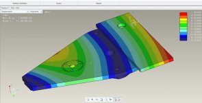
I looked at various designs initially using aluminium. My LP12 already has a prototype sub-chassis I made earlier in the year from two sheets of ally spaced apart 8mm. This is quite stiff but can be improved. I looked at birch ply as a material and this immediately seemed far better than any aluminium design. The material is light and comparatively stiff so can be made thicker and hence stiffer. A simple flat 18mm sheet is very stiff and the comparative mode frequency jumps to ~110Hz compared to 91Hz for Keel. The latest version of this I now have takes this as far as I can go within 1.1kgs mass. The first mode frequency is up to 128Hz. Its 24mm thick in the centre area thinning out at the edges. This gives the highest stiffness and I can get in the sub chassis. A standard Linn Rega armboard is used and a steel bush in the centre to allow the bearing to be bolted in. All of the parts will be bolted and bonded together. Images of the FEA simulation are below.
For my design I aimed to make it as stiff as possible while holding weight to same as the standard item. All aftermarket options seem to be around 1.1kgs. The suspension springs are marginally overloaded as it is, so just adding weight to make the sub chassis stiffer is not possible. It also needs to be something I can make for reasonable effort and cost. What I have ended up with is around twice as stiff as Keel and within 1.1kgs mass. I can make it in the garage with a days work and total cost will be within £30
I looked at various designs initially using aluminium. My LP12 already has a prototype sub-chassis I made earlier in the year from two sheets of ally spaced apart 8mm. This is quite stiff but can be improved. I looked at birch ply as a material and this immediately seemed far better than any aluminium design. The material is light and comparatively stiff so can be made thicker and hence stiffer. A simple flat 18mm sheet is very stiff and the comparative mode frequency jumps to ~110Hz compared to 91Hz for Keel. The latest version of this I now have takes this as far as I can go within 1.1kgs mass. The first mode frequency is up to 128Hz. Its 24mm thick in the centre area thinning out at the edges. This gives the highest stiffness and I can get in the sub chassis. A standard Linn Rega armboard is used and a steel bush in the centre to allow the bearing to be bolted in. All of the parts will be bolted and bonded together. Images of the FEA simulation are below.
Attachments
- Home
- Source & Line
- Analogue Source
- A few mods to my LP12