Happy new year all.
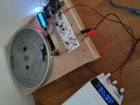
I have made some progress with my dc motor drive. I made a test rig to develop a drive circuit and the Arduino program. Its controlling speed really well, very close to target speed. I made a pulley for the motor myself on my lathe. Its 17mm diameter, which was an arbitrary choice to get it running, but seems about right. The motor needs around 2.4 and 3.3 volts to run at 33.3/45rpm with this pulley on the Linn. The test rig I have put together uses a SR222 platter which I picked up cheap on ebay. Its a different diameter so target speeds on the rig are set to 42 and 57 rpm to give an equivalent motor rpm. Once working and optimised it will be an easy job to swap it over and fine tune it for the Linn. The drive circuit uses two op amp stages and a transistor. Its simple but seems to be working well. Im not great with electronics so I'm pleased to have got this far. The first op amp stage has a voltage adder to get more range out of the Arduino DAC output. This has a 12-bit range, so a value of 0 to 4096, and 0.55 to 2.7 volts. The circuit I have converts this to around 2.2 to 3.5 volts so for 33.3/45 rpm the DAC is operating between ~400 and ~3600 which should give a resolution of 0.004 rpm. This is what I am seeing in the measured speed - its usually holding the speed within 0.002 rpm of target. Im measuring speed with a hall sensor with a single magnet, using the micros() function in the Arduino to get good resolution on the measurement. For speed control I let the platter turn 5 revolutions before making adjustments. It takes ~4 revs to get up to near nominal speed. Its usually within 0.01rpm of target speed at rev 6, and 0.002 after 30 seconds. Good enough?
The second op amp adds torque feedback so the drive voltage to the motor increases when load is added. This seems to work well. I need to add a tonearm to measure how much speed will change when the stylus is dropped onto the record. There is a bit of optimisation to do on this yet.
Next step is to add a memory card into the Arduino and get it recording hours run. Im going to mount a memory card somewhere onto the LP12 so I can periodically check hours run to manage life on the cart.
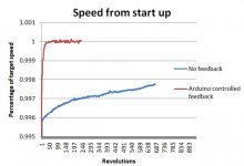
The graph below shows a trace of the speed showing how well its working. With no feedback the motor speed gradually increases with time, assume as it warms up.
I have made some progress with my dc motor drive. I made a test rig to develop a drive circuit and the Arduino program. Its controlling speed really well, very close to target speed. I made a pulley for the motor myself on my lathe. Its 17mm diameter, which was an arbitrary choice to get it running, but seems about right. The motor needs around 2.4 and 3.3 volts to run at 33.3/45rpm with this pulley on the Linn. The test rig I have put together uses a SR222 platter which I picked up cheap on ebay. Its a different diameter so target speeds on the rig are set to 42 and 57 rpm to give an equivalent motor rpm. Once working and optimised it will be an easy job to swap it over and fine tune it for the Linn. The drive circuit uses two op amp stages and a transistor. Its simple but seems to be working well. Im not great with electronics so I'm pleased to have got this far. The first op amp stage has a voltage adder to get more range out of the Arduino DAC output. This has a 12-bit range, so a value of 0 to 4096, and 0.55 to 2.7 volts. The circuit I have converts this to around 2.2 to 3.5 volts so for 33.3/45 rpm the DAC is operating between ~400 and ~3600 which should give a resolution of 0.004 rpm. This is what I am seeing in the measured speed - its usually holding the speed within 0.002 rpm of target. Im measuring speed with a hall sensor with a single magnet, using the micros() function in the Arduino to get good resolution on the measurement. For speed control I let the platter turn 5 revolutions before making adjustments. It takes ~4 revs to get up to near nominal speed. Its usually within 0.01rpm of target speed at rev 6, and 0.002 after 30 seconds. Good enough?
The second op amp adds torque feedback so the drive voltage to the motor increases when load is added. This seems to work well. I need to add a tonearm to measure how much speed will change when the stylus is dropped onto the record. There is a bit of optimisation to do on this yet.
Next step is to add a memory card into the Arduino and get it recording hours run. Im going to mount a memory card somewhere onto the LP12 so I can periodically check hours run to manage life on the cart.
The graph below shows a trace of the speed showing how well its working. With no feedback the motor speed gradually increases with time, assume as it warms up.
Attachments
If ivor was worried about stability in the springs why didn't he just use wider coils?
Dean, yeh dc motors drift as they warm up, thats why the OL kits with tacho feedback are useless.
Dean, yeh dc motors drift as they warm up, thats why the OL kits with tacho feedback are useless.
I have been asked to post the Arduino code so that's in the attachment. Its about finished, as optimised as I can get it. I have put about 50 hours running on the motor and have tried various control options. The latest has speed adjustment starting after rev 4 and continues every revolution for next 20 with a diminishing magnitude. Thereafter it records average speed and makes a minor adjustment every 5 revs. Once its running steady state its stable and holds average speed well, within 0.002rpm of target. Motor speed drifts more during start up hence the adjustment every rev during that phase. Instantaneous speed does drift around a bit - in range 33.329 to 33.337 rpm. Is that good/bad/ok - keen to get a view on it? The circuit diagram is shown below. Im now making parts - motor housing, new pulley, pcb - will post more details soon.
Attachments


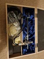
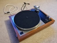
I have just about finished this project now. The turntable is assembled, working and sounding great. Its been a while since the last post but there were a few setbacks and the job was dropped in favour of a house extension project. Setbacks included 3 failed Arduino boards, one of which was self imposed. Im on my 3rd motor too which is more painful since they are over £200 each. I damaged one motor fitting a pulley and then switched to a slighly different motor version. MAXON make a long and short version of the DCX motor. The short version is what I now have which is best IMO since it is easier to integrate and datasheet shows it to be quieter. Im on iteration 3 of the PCB, which is a shield fitted on top of the DUE. Making pulleys has been a regular feature. I must have made 30 different pulleys with differnet diameters, shapes and materials. The final version is dia 16mm in aluminium with a slight barrelled shape. Making the pulley perfectly concentric has been challenging but I now have that perfected.
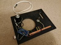
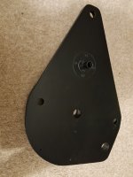
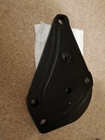
The mods are built into a 3/4" plywood baseplate that houses the motor and electronics. Power comes from dc out from my preamp so there are no external boxes, which was one of the aims I had. The motor is fitted into a 1kg steel housing in strips of sorbothane. There is a steel post also supporting the free edge of the top plate, and a corresponding hole through the subchassis. The top plate also has a stiffening ring of 2mm stainless added. I made the subchassis by laminating pieces of birch ply and there is a steel housing screwed and glued in the centre with the linn bearing glued and screwed into that.
The motor is quiet with no noticeable vibration. Speed stability is usually within 0.02% once running and stable. Now its built into a functioning turntable I have measured the speed while lowering the tonearm and was surprised to see a momentary dip close to 1% which recovers back after a few revs.
Attachments
-
 20220103_181035 - Copy.jpg488.4 KB · Views: 213
 -
 20220103_181046 - Copy.jpg213.5 KB · Views: 223
 -
 20220103_181455 - Copy.jpg332.5 KB · Views: 224
 -
 20220103_181504 - Copy.jpg344.9 KB · Views: 218
 -
 20220103_183141.jpg483 KB · Views: 226
 -
 20220105_080907 - Copy.jpg456.9 KB · Views: 217
 -
 20220105_083231.jpg357.5 KB · Views: 223
check out post #14 under
https://www.diyaudio.com/community/threads/re-linn-cirkus-bearing-set.117427/
https://www.diyaudio.com/community/threads/re-linn-cirkus-bearing-set.117427/
I damaged one motor fitting a pulley and then switched to a slightly different motor version.
The guy that made the pulleys for the Rega 24v AC Premotec motors I use on my 'SkeletaLinn' - with a 'Number9' speed controller - made them with a central hole that was fractionally larger than the motor spindle ... so it fitted on without force. He then drilled 3x tapped holes for grub screws to clamp onto the spindle.
Works well! 🙂
Andy
MAXON make a long and short version of the DCX motor.
Could you share the exact model? Wondering if a tacho option is worth having.
Disappointing the DCX speed drops so much under LP playing load. My half power 110189 behaves similarly, the speed, without fb correction drops from 33.3 to about 33.1 rpm.
Currently using the simple current fb circuit by Martin Clarke, described in the Pink fish media thread. It is possible to set it up, so it almost completely absorbs the average load induced speed variation, but at the cost of a higher short term instability, at least with my rather heavy platter.
The funny thing is the dc motor sounds subjectively better to me than any of the ac motors i have at hand and slaughters the bdsl motors i've tried. Could this be similar to having a preference for high jitter dacs? 🙂
Perhaps a test record suited for w&f measurements is essential if one gets serious about the issue. Like this one
I think the speed dip from stylus drag is not the fault of the motor. The circuit shown at #23 has passive speed control and you can tweak the balance resistor (see r1,3,4) value to make it compensate for load better. The next circuit I make will include fine adjustment there so the speed drop could be dialled out. The stability of the motor speed under load is all about the circuit, not the motor. If you drive the motor with a straight dc supply it’s pretty hopeless at spinning the platter up quickly and dealing with variation in load. The best approach is to use an effective passive constant speed circuit with closed loop active speed control on top.
I have tried DCX22L and S versions, both 24v with PM brushes. The short motor has gone awry so I’m now using the 22L which is working ok for now. Maxon has told me these motors are not suited to being run so slowly, so that’s not good.
I have tried DCX22L and S versions, both 24v with PM brushes. The short motor has gone awry so I’m now using the 22L which is working ok for now. Maxon has told me these motors are not suited to being run so slowly, so that’s not good.
Last edited:
Many thanks for your comments Dean. Even if they are a little discouraging 🙂
Always thought the main reason for A-max motors dying early was the lateral load from the belt, which is greatly improved in the DCX. Slow speed is also a problem? Something to do with lubrication?
This kind of compensation works fine under static conditions. Once you have the belt compliance with the attached inertia of the platter things get more complicated. Any disturbance in the drag initiates a response. Perhaps not a serious issue with the Linn, but with a much heavier platter and a longer belt some integration becomes essential.
Always thought the main reason for A-max motors dying early was the lateral load from the belt, which is greatly improved in the DCX. Slow speed is also a problem? Something to do with lubrication?
The circuit shown at #23 has passive speed control and you can tweak the balance resistor (see r1,3,4) value to make it compensate for load better.
This kind of compensation works fine under static conditions. Once you have the belt compliance with the attached inertia of the platter things get more complicated. Any disturbance in the drag initiates a response. Perhaps not a serious issue with the Linn, but with a much heavier platter and a longer belt some integration becomes essential.
Deano,Wow that's radical! Love it. Some out of the box thinking has gone into your version.
I have thought about a double motor, or adding an idler pulley to balance the loads on the platter. I know the single motor/pulley does pull the sub chassis from its 'free' position a little. This must influence the behaviour of the suspension. I will see if that could work in my design.
I know that getting a good connection between the platter and arm is key so I have been looking at that area carefully. The Keel seems to be the best off the shelf upgrade option so I looked at that design, did a CAD model of it and some FEA. Its stiffer than the pressed steel version but I was surprised its not as good as I expected. It has a resonance of 91Hz - see image below. The FEA setup I did has the sub chassis fixed vertically at the 3x springs and the weight of the tonearm and platter added. Its therefore hanging from the springs which are effectively fixed points in the simulation.
It's interesting to see that you made a model of Keel and did analysis.
I am trying to make a sub-chases some thing similar to Keel for my self. It would be great if you can share some information like centre of gravity and any other important information on Keel
Did you consider the Maxon DCX with encoder and Escon control board to regulate speed. I had some of the maxon sales team pop by and show me a demo.
I think this is what Kronos use?
I think this is what Kronos use?
No I have had no problems with lubrication or bearings. Its something to do with the brushes, but I dont know the failure mechanism. The 22S motor worked well to start with conrolling speed accurately. When working well the speed was holding 33.3333 plus/minus 0.05 rpm with the proportional drive behaving as expected. After a while the 0.05rpm variance started to increase and when logging the speed you could see it worsening with 33.1, 33.0 instantaneous speed readings creaping in which start to become audible, and degraded from there. Something was changing in the motor but i dont knowwhat. The terminal resistance always measured consistent at 16 ohms. I contacted Maxon technical department a few times and eventually got this response...Slow speed is also a problem? Something to do with lubrication?
Hi Mark
The problem lies with the low input power, not just voltage but current as well. What we have found on other turntable motors is that a gold flashed brush works better. This would require a new modified motor creating ad is a lot of work for a few motors.
So thats not good they are saying standard motors available to the public are not suited to being run slowly and you need a special motor. It seems turntable manufacturers pay for development of special motor versions. The Linn Radikal 1 is a 'special' RE Max motor and Radikal 2 is a DC-Max26, introduced after the former went obsolete.
He did sell me Linn Radikal 1 motor off the back of this dialogue so that one positive.
Last edited:
I'm glad you enjoyed it. I too had a plain vanilla 24 year old LP12, Valhalla and Ittok LV. All black.
When I upgraded it, I decided to go OEM... But used.
It took me a few years but I found a very well price Lingo with a spare motor and two new belts.
I had the Lingo installed, tried the new and old motor, stayed with the old one. Put a Trampolin v2, new suspension springs and re did the mounting of the Grado Master 2. I had all of this done by a local guy who knows such things ( I'm in SoCal ). All in all, cost me about 1400 bucks with parts and labor and about 5 months... The sound of the table is now fantastic.
I realize your quest, but like the other guy said, you might have done all of this work on a broken down table and kept this one as reference (or upgrade it).
Next, I will spring for the Karousel.
No I didnt,I wasnt aware of this controller when i started the exercise. Looks good. Are all these controllers using PWM supply though?Did you consider the Maxon DCX with encoder and Escon control board to regulate speed. I had some of the maxon sales team pop by and show me a demo.
I think this is what Kronos use?
I created a CAD model as close as i could scaling from photographs. I found a website where someone published a measured weight figure so this was key to guide the geometry. My CAD model is 22mm thick overall, 10mm for armboard and 12mm for the main section. Where the aluminium is machined out its 3mm thick. The CAD model massis 1.13kg. I think all LP12 subchassis are around 1.1kg mass. Any higher the springs bottom out, so 1.1 is the limit. I have attached a .stp file.Deano,
It's interesting to see that you made a model of Keel and did analysis.
I am trying to make a sub-chases some thing similar to Keel for my self. It would be great if you can share some information like centre of gravity and any other important information on Keel
Attachments
when logging the speed you could see it worsening with 33.1, 33.0 instantaneous speed readings
My A-max started behaving the same way and i assumed the negative resistance circuit was to blame. The driving voltage is very stable when the motor is idling but once it has to drive the platter the driving voltage starts constantly changing. I assumed electric instability but perhaps it is the brushes contact resistance that is changing as the motor spins under load and the drive system just tries to compensate for that.
Many thanks for your observations and disclosing the response from Maxon. The motor used in the Continuum is said to be a 60v, carbon brushes model which is a little at odds with the gold flash.
Perhaps even the OL Maxon based kits use an off the shelf motor. Inexplicable that Maxon would not have a regular motor suited for low rpm work.
The earlier 36/2 controller uses PWM
The new ones seems to be different?
https://www.maxongroup.com/maxon/view/news/EPOS4-positioning-controller
From memory the engineer was leading me to the higher read per minute encoder, I can't seem to see it now, but I'm sure it was 16k per revolution, and as you have chosen, sintered bearing and precious metal brushes.
The rep seemed to imply it would be fairly easy to build an LED board to show speed or at least a green/red/blue light to show fluctuation in speed.
The encoders are bonded onto the motors at the factory so I believe can't just be added. A few years ago they said they could supply direct, minimum order was only 2 units, and can just be configured online.
I believe this is the system Kronos use in their £25k TT's, its about £360 all in for the original controller, would need a DC power supply.
Interesting approach from Continium. That's the original Maxon Eschon 36/3 controller they are using. But 36mm 60v Motor with ball bearings and graphite brushes.
"The 35mm, 60-volt DC motor was designed and manufactured specifically for optimum performance with Obsidian’s platter mass and physical harmonic characteristics. It combines a set of specifications uncommon for low-noise applications, but that combine to deliver exceptionally smooth operation and the highest power currently available in a motor of its size. Its zero-cogging motor is controlled by a servo amplifier running at 53.6 kHz, far above the range of audibility.
The Quiet One uses stainless steel pre-loaded ball bearings. Why ball bearings, when sleeve bearings are typically preferred for low-noise applications? Because sleeve bearings do not have the load handling or durability of ball bearings—and through careful design, our dream team was able to ensure that any vibrations created by the bearings would be damped by other components in Obsidian’s structure.
The Quiet One uses graphite brushes. Why graphite, when precious metal brushes are typically preferred? Because precious metal brushes often do not have the current conducting capacity required to drive a heavy platter—and because our dream team created a special damping system, calibrated precisely for the motor’s speed range, that attenuates brush noise."
http://www.continuumaudiolabs.com/turntables/obsidian/innovative_motor.php
Thank you very much for the information and the drawing. Really appreciate it.No I didnt,I wasnt aware of this controller when i started the exercise. Looks good. Are all these controllers using PWM supply though?
I created a CAD model as close as i could scaling from photographs. I found a website where someone published a measured weight figure so this was key to guide the geometry. My CAD model is 22mm thick overall, 10mm for armboard and 12mm for the main section. Where the aluminium is machined out its 3mm thick. The CAD model massis 1.13kg. I think all LP12 subchassis are around 1.1kg mass. Any higher the springs bottom out, so 1.1 is the limit. I have attached a .stp file.
I took the Sheet Metal Sub-Chases dimensions on a CMM and wanted to make a drawing with the photos as you did. But you saved all of that. I will see how to go forward with manufacturing.
Kindly suggest if you have any information on which aluminium alloy is better. Does something like 6061-T6 or 2014-T6 works?
https://www.easycomposites.co.uk/foam-cored-carbon-fibre-panel
This above link was going to be one of my test sub-chassis materials. I believe FunkFirm use something similar in their Linn upgrade. It should be incredibly stiff, with almost no mass so far less stored energy. Not sure what the resonant frequency is.
https://www.tapatalk.com/groups/audioqualia/damping-factor-values-t29.html
I really like the above blog, it lists, frequency, damping factor, transmissibility of most major materials specifically relating to turntable plinths.
- Home
- Source & Line
- Analogue Source
- A few mods to my LP12