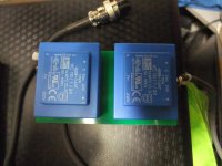
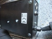
From a friend I got for repair a diy motor control for Linn's LP-12.
Compared to the X-tal versions with divider from Linn model "Valhalla" and "Lingo" is here a sine wave generator in use - similar to Linn's AXIS motor control - go to
http://www.turntablepsu.com/images/Axis Schematic.pdf
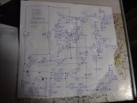
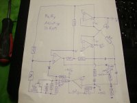
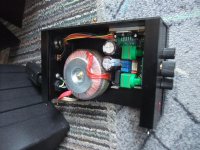
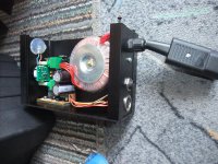
In the attachment you will find the schematics, which I have drawn out.
Who can give a description, how the circuit of the sine wave generator works or can give an advice, whether this circuit was based on an existing commercial product.
Thank you very much therefore.
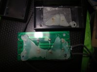
P.S.: The reason for not correct working condition you will find in the fifth image.
Go to post #16 for news and new schematic, which I have drawn out.
Compared to the X-tal versions with divider from Linn model "Valhalla" and "Lingo" is here a sine wave generator in use - similar to Linn's AXIS motor control - go to
http://www.turntablepsu.com/images/Axis Schematic.pdf
In the attachment you will find the schematics, which I have drawn out.
Who can give a description, how the circuit of the sine wave generator works or can give an advice, whether this circuit was based on an existing commercial product.
Thank you very much therefore.
P.S.: The reason for not correct working condition you will find in the fifth image.
Go to post #16 for news and new schematic, which I have drawn out.
Attachments
-
 DSCF5318.jpg853.7 KB · Views: 890
 -
 DSCF5324.jpg532.3 KB · Views: 832
 -
 DSCF5322.jpg988.6 KB · Views: 808
 -
 DSCF5315.jpg768.8 KB · Views: 768
 -
 DSCF5230.jpg1 MB · Views: 748
 -
 DSCF5207.jpg985.6 KB · Views: 365
 -
 DSCF5209.jpg1,008.5 KB · Views: 325
 -
 DSCF5208.jpg1,008.9 KB · Views: 327
 -
 DSCF5240.jpg1,010.4 KB · Views: 330
 -
 DSCF5249.jpg1,005.1 KB · Views: 354
Last edited:
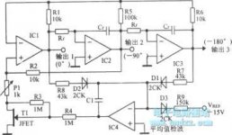
It's hard to tell from your hand drawn schematic, but the original Axis controller was essentially a state variable filter with 2 back to back integrators and feedback to produce oscillations and a 0° and 90° output. In order to be stable and limit the output to a sinewave, the feedback network is either fixed (cheap and cheerful way of doing it) or uses an AGC circuit (better control of Q and output level). The RC time constant formed by the feedback cap in the integrator and the input resistor determine the frequency.
A good description of the circuit can be found Here; page 4 of the PDF breaks down the description of a state variable filter used as an oscillator.
A good description of the circuit can be found Here; page 4 of the PDF breaks down the description of a state variable filter used as an oscillator.
Thank you for your information.
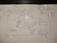
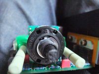
In the attachment you will find a simplified schematic (oscillator only without output gain stages so as without variable resistor networks for two speeds and without power supply.
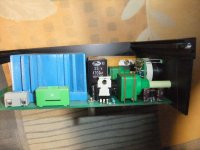
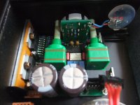
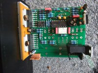
After cleaning and and re-soldering of various solder joints on solder site the motor control works now fine without any temporarily occurred unwanted effects (tested only with a single motor as to see under
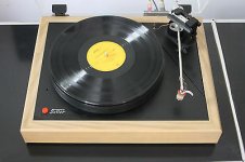
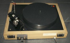
Plattenspieler Motor (Rega, Linn), Hifi-Klassiker - HIFI-FORUM - first image).
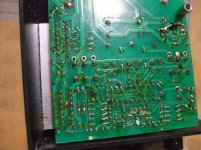
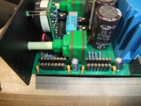
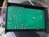
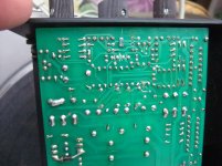
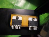
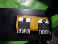
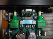
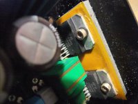
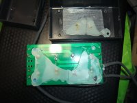
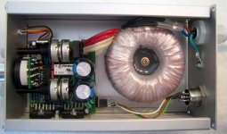
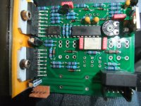
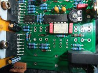
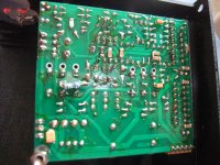
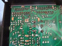
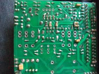
the second and third image from my attachment shows the PCB after my service.
I will report concerning the results by listening test in the next weeks.
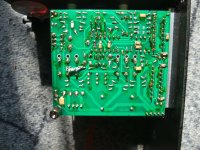
P.S.: One of both LED's (fourth image) is drawn in the wrong direction.
In the attachment you will find a simplified schematic (oscillator only without output gain stages so as without variable resistor networks for two speeds and without power supply.
After cleaning and and re-soldering of various solder joints on solder site the motor control works now fine without any temporarily occurred unwanted effects (tested only with a single motor as to see under
Plattenspieler Motor (Rega, Linn), Hifi-Klassiker - HIFI-FORUM - first image).
the second and third image from my attachment shows the PCB after my service.
I will report concerning the results by listening test in the next weeks.
P.S.: One of both LED's (fourth image) is drawn in the wrong direction.
Attachments
Last edited:
Last weekend I have heard this device against the last version from Linn's Lingo. There were at whole 3 music lovers in this listening test. Record Player was Linn's LP12, Tornarm Morch DP-6 and cartridge Audio Technica's ART-9.
The result was unanimous - sonic quality was better in all respects with the homebrew (diy) version.
The most striking feature was the improved spatial representation of voices and instruments.
This evening I receive a PM. Here it was written that the circuit from my created schematic on this device based on the approach of Dr. Fuß - go to
Linn Lingo vs. Dr. Fuß or Square-Wave vs. Sine Wave Oscillator for Motor Control
Last edited:
Many years ago I built a squarewave to sin/cos-converter based on switched capacitor filter IC LTC1065. With a little bit of HC logic it is possible to derive pretty precise Sinewaves from a precise clock with almost no other external circuitry.
The application was pretty similar: A synchronous motor driven by two linear power amplifiers for extremely constant speed and low wow/flutter.
After changing over to a simple little microcontroller (PIC12C508 or the like) to generate the two phase shifted square waves and a 100x as high reference clock for the Switched C-filter, I had a rather cheap two chip (2xPDIP8) solution for a crystal stable SIN/COS generator.
Last edited:
State variable oscillators are pretty tricky for stabilizing their amplitude without clipping the sine wave etc.
Here you can find some Theory:
http://ww1.microchip.com/downloads/en/Appnotes/00866a.pdf
Some elaborate designs to cope with stabilization while maintaining low distortion can be found in Linear technology's AN-67 Sine oscillator or in Hameg's HM8037 sine generator service manual.
https://www.google.com/url?sa=t&rct...037-serv.pdf&usg=AOvVaw2QSw8VuOY78pWGmFxlTJLx
With a little tuning of this circuit -120dB THD can be squeezed out of a HM8037.
Last edited:
Thank you very much for all hints.
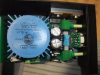
Here the remaining images so as (in the following posting) some images from the genuine motor control device:
Here the remaining images so as (in the following posting) some images from the genuine motor control device:
Attachments
Dr. Fuß (Music Components) Genuine Device
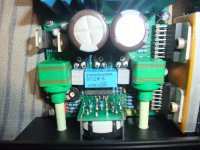
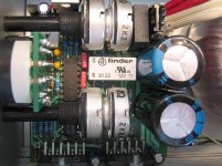
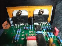
the difference should be clearly visible. Other transformer, other PCB, other monolithic power amp IC (LM4700 instead TDA7293) and probably other schematic.
the difference should be clearly visible. Other transformer, other PCB, other monolithic power amp IC (LM4700 instead TDA7293) and probably other schematic.
Attachments
Last edited:
Did you check the frequency, filter based oscillators are only as accurate as the components used? A few percent fast could sound much more funLast weekend I have heard this device against the last version from Linn's Lingo. There were at whole 3 music lovers in this listening test. Record Player was Linn's LP12, Tornarm Morch DP-6 and cartridge Audio Technica's ART-9.
The result was unanimous - sonic quality was better in all respects with the homebrew (diy) version.
The most striking feature was the improved spatial representation of voices and instruments....
yes - I use this equipment from Linn:
https://www.diyaudio.com/forums/ana...robe-questions-circuit-diagr.html#post6005631
https://www.diyaudio.com/forums/ana...robe-questions-circuit-diagr.html#post6005631
Last weekend I have heard this device against the last version from Linn's Lingo. There were at whole 3 music lovers in this listening test. Record Player was Linn's LP12, Tornarm Morch DP-6 and cartridge Audio Technica's ART-9.
The result was unanimous - sonic quality was better in all respects with the homebrew (diy) version.
The most striking feature was the improved spatial representation of voices and instruments.
This evening I receive a PM. Here it was written that the circuit from my created schematic on this device based on the approach of Dr. Fuß - go to
Linn Lingo vs. Dr. Fuß or Square-Wave vs. Sine Wave Oscillator for Motor Control
Again a listening test with this home brew motor control - this time against a Lingo from the first edition - go to
http://www.turntablepsu.com/images/Lingo Schematic.pdf
and
Linn Lingo schematic
and against a modified power supply from Linn Axis - go to
Repairing Linn Axis Motor Drive Amplifier
The modifications by the "AXIS" motor control consisted of changing the resistors R 50 and R 33 with potentiometers to adjust the correct value for the motor voltage and the right value of RpM (only tested "33" mode) - go to
Linn Axis Schematic
Both the Lingo and the motor control of Linn's AXIS are equipped with new caps.
The turntable wasn't a Linn LP12 but the model "SOLIST" from the no longer exist German company "Audiokonstruktion" - go to the attached images (the same model but an other device on the images).
The used arm was a SME-V and the cartridge a three months old ART-9 from Audio Technica.
The differences in sonic quality between the Lingo and the homebrew version were largely the same as in the listening test mentioned before with LP-12.
It is very astonishing that the audible differences between the homebrew version and Linn's Axis motor control were surprisingly small (the music representation went more in breadth and a bit too little in depth) and between the LINGO and Linn's Axis motor control were very clearly to the disadvantage of the LINGO, which sounded more dynamic at first glance, but ultimately conveyed the tendency towards hardness and spatial representation appeared flat.
Unfortunately I don't have the vocabulary of Mr. John Atkinson (stereophile) due my still bad english - otherwise I could write better and above all a more detailed report of this listening test result.
At first reason therefore I suspected that the motor voltage on the Lingo was too high, but which was not the case (genuine value 60VAC already reduced to 24VAC - same value than on AXIS motor control - both after start-up measured).
Also the phase shift between the motor winding coils are correct at both control units.
LINGO power supply units in genuine condition delivers 60VAC for the motor, that means more drive power for the motor, but worse sound quality due more motor hum, which was confirmed in several past listening tests.
Next step is to modify the AXIS power supply in such case, that the low voltage supply was created by a separat transformer and rectifier (this parts replace the hot 15K power resistors) and replacing the 33uF/47uF caps by 375VAC MKP motor caps.
Let's see what else is going on here.
However, it is clearly clear that the LINGO motor control (which is not faulty) is inferior to the power supply resp. motor control for the Linn AXIS - check also out fig. 1-3 under
https://www.stereophile.com/content/linn-lp-playing-system-measurements
Attachments
Last edited:
good advice. This circuit diagram is closest to that of my drawingIt's hard to tell from your hand drawn schematic, but the original Axis controller was essentially a state variable filter with 2 back to back integrators and feedback to produce oscillations and a 0° and 90° output. In order to be stable and limit the output to a sinewave, the feedback network is either fixed (cheap and cheerful way of doing it) or uses an AGC circuit (better control of Q and output level). The RC time constant formed by the feedback cap in the integrator and the input resistor determine the frequency.
A good description of the circuit can be found Here; page 4 of the PDF breaks down the description of a state variable filter used as an oscillator.
ESP - Sinewaves
Again I got for repair a diy motor control for Linn's LP-12 looks similar but not identical to those version described in post #1
Attachments
-
 MC Motor Control Front.jpg991.9 KB · Views: 268
 -
 MC Motor Control Rear.jpg1,001.5 KB · Views: 262
 -
 MC Motor Control Top View-I.jpg1,015.3 KB · Views: 248
 -
 MC Motor Control Top View-II.jpg1 MB · Views: 98
 -
 MC Motor Control Toroidal-I.jpg846.3 KB · Views: 124
 -
 MC Motor Control Toroidal-II.jpg1,017.3 KB · Views: 94
 -
 MC Motor Control Sticker.jpg1,010.7 KB · Views: 82
 -
 MC Motor Control Speed Select.jpg996.8 KB · Views: 98
 -
 MC Motor Control Speed Select-II.jpg985.3 KB · Views: 106
 -
 MC Motor Control 2xTDA7293.jpg995.9 KB · Views: 112
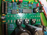
now the images of PCB before and after service.
Attachments
-
 MC Motor Control Strip Down-I.jpg1,000.9 KB · Views: 118
 -
 MC Motor Control Strip Down-II.jpg1,009.8 KB · Views: 101
 -
 MC Motor Control Strip Down-III.jpg1,017.5 KB · Views: 99
 -
 MC Motor Control Strip Down-IV.jpg1,004.2 KB · Views: 82
 -
 MC Motor Control Strip Down-V.jpg1 MB · Views: 87
 -
 MC Motor Control Solder Side before Service-I.jpg993.8 KB · Views: 81
 -
 MC Motor Control Solder Side before Service-II.jpg1,007.1 KB · Views: 105
 -
 MC Motor Control Solder Side before Service-III.jpg1,021.5 KB · Views: 103
 -
 MC Motor Control Solder Side after Service-I.jpg1,019.7 KB · Views: 93
 -
 MC Motor Control Solder Side after Service-II.jpg1 MB · Views: 88
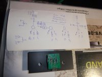
both hand drawn schematic from post #1 and post #3 (simplified schematic) contain too many mistakes.
Furthermore, the arrangement of the parts in my drawing makes it nearly impossible to understand the theory of operation according a SVF based sine wave oscillator.
By chance I have found the corresponding descriptions on the web - go to the book
Elemente der angewandten Elektronik: Kompendium fur Ausbildung und Beruf (Viewegs Fachbucher der Technik) von Erwin Bohmer
on pages 208 and209 unter
Elemente der angewandten Elektronik: Kompendium fur Ausbildung und Beruf - Erwin Bohmer, Dietmar Ehrhardt, Wolfgang Oberschelp - Google Books
and the attached files (the PDF shows my new drawing of the motor control device from my previous two posts).
I have it translate in the english language:
1) German:
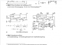
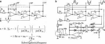
Ein RC-Oszillator mit drei Sinusausgängen gleicher Amplitude und einer Phasenverschiebung von jeweils 90° ist der sog. Quadraturoszillator nach Bild 3. Er geht aus einem State Variable Filter (SVF) hervor, wenn man mit X = 0 die Polgüte unendlich groß macht.
In diesem Fall ist die Rückkoppelung vom Bandpass-Ausgang unwirksam Es bleibt nur eine Schleife mit der angeschriebenen Verstärkung Vs über den Inverter und die beiden folgenden Integrierer.
Sofern man vom Bandpass-Ausgang über den Schalter "S" eine Rückkoppelung auf den "N" Eingang des Inverters herstellt (gestrichelt in fig. a) kann die Schaltung bereits bei X > 0 schwingen.
Man nutzt diese Möglichkeit der Amplitudenregelung, wobei man die Widerstandseinstellung wie in fig. b automatisch über einen J-FET ausführen läßt. Dieser ist hier mit den Widerständen R1 und R2 beschaltet.
Er wird gesteuert von einem als PI Regler beschalteten Operationsverstärker, der zur Unterdrückung der Welligkeit am Ausgang zusätzlich mit einem 1µF Kondensator beschaltet ist.
Die parallel liegende Diode verhindert ein Umschwingen in die positive Sättigung.
Im stationären Schwingbetrieb ist der Mittelwert des über die Dioden D1 und D2 zufließenden Stromes gleich dem vom Sollwertpotentiometer abgezogenem Strom.
Diode D3 dient lediglich zur Temperaturkompensation von D1 und D2. Daher ist die Amplitudeneinstellung weitgehend temperaturunabhängig.
2) English:
A RC sine wave oscillator with three outputs of the same amplitude and a phase shift of each 90° is the so-called quadrature oscillator as shown in fig. 3 (attached image 3+4). It is basically a state variable filter (SVF) when the pole quality is infinity with X = 0.
In this case the feedback from the bandpass output is not present. Only one loop remains with the indicated gain Vs via the inverter and the two following integrators.
If a feedback is established from the band pass output via switch "S" to the "N" input of the inverter (dashed line in fig. a, attached image 3+4), the circuit can already oscillate at X > 0.
This option of amplitude control is used, with the resistance setting as shown in fig. b can be carried out automatically via a J-FET. This J-FET is additional equipped here with the resistors R1 and R2. It is controlled by an operational amplifier worked as a PI controller, which is additionally wired with a 1µF capacitor to avoid the ripple at the output.
The parallel diode prevents shifting into positive saturation. In steady-state oscillating operation, the average value of the current flow through both diodes D1 and D2 is equal to the current drawn from the setpoint potentiometer.
Diode D3 is only used for temperature compensation of D1 and D2. The amplitude setting is therefore largely independent of temperature.
I don't understand the marked terms both in English and German exactly.
The main question in the moment is in this case, how is to adjust Tr 4 - go to the attached PDF of my drawing. Because this part is defective resp. faulty, I don't know the original position.
Furthermore, the arrangement of the parts in my drawing makes it nearly impossible to understand the theory of operation according a SVF based sine wave oscillator.
By chance I have found the corresponding descriptions on the web - go to the book
Elemente der angewandten Elektronik: Kompendium fur Ausbildung und Beruf (Viewegs Fachbucher der Technik) von Erwin Bohmer
on pages 208 and209 unter
Elemente der angewandten Elektronik: Kompendium fur Ausbildung und Beruf - Erwin Bohmer, Dietmar Ehrhardt, Wolfgang Oberschelp - Google Books
and the attached files (the PDF shows my new drawing of the motor control device from my previous two posts).
I have it translate in the english language:
1) German:
Ein RC-Oszillator mit drei Sinusausgängen gleicher Amplitude und einer Phasenverschiebung von jeweils 90° ist der sog. Quadraturoszillator nach Bild 3. Er geht aus einem State Variable Filter (SVF) hervor, wenn man mit X = 0 die Polgüte unendlich groß macht.
In diesem Fall ist die Rückkoppelung vom Bandpass-Ausgang unwirksam Es bleibt nur eine Schleife mit der angeschriebenen Verstärkung Vs über den Inverter und die beiden folgenden Integrierer.
Sofern man vom Bandpass-Ausgang über den Schalter "S" eine Rückkoppelung auf den "N" Eingang des Inverters herstellt (gestrichelt in fig. a) kann die Schaltung bereits bei X > 0 schwingen.
Man nutzt diese Möglichkeit der Amplitudenregelung, wobei man die Widerstandseinstellung wie in fig. b automatisch über einen J-FET ausführen läßt. Dieser ist hier mit den Widerständen R1 und R2 beschaltet.
Er wird gesteuert von einem als PI Regler beschalteten Operationsverstärker, der zur Unterdrückung der Welligkeit am Ausgang zusätzlich mit einem 1µF Kondensator beschaltet ist.
Die parallel liegende Diode verhindert ein Umschwingen in die positive Sättigung.
Im stationären Schwingbetrieb ist der Mittelwert des über die Dioden D1 und D2 zufließenden Stromes gleich dem vom Sollwertpotentiometer abgezogenem Strom.
Diode D3 dient lediglich zur Temperaturkompensation von D1 und D2. Daher ist die Amplitudeneinstellung weitgehend temperaturunabhängig.
2) English:
A RC sine wave oscillator with three outputs of the same amplitude and a phase shift of each 90° is the so-called quadrature oscillator as shown in fig. 3 (attached image 3+4). It is basically a state variable filter (SVF) when the pole quality is infinity with X = 0.
In this case the feedback from the bandpass output is not present. Only one loop remains with the indicated gain Vs via the inverter and the two following integrators.
If a feedback is established from the band pass output via switch "S" to the "N" input of the inverter (dashed line in fig. a, attached image 3+4), the circuit can already oscillate at X > 0.
This option of amplitude control is used, with the resistance setting as shown in fig. b can be carried out automatically via a J-FET. This J-FET is additional equipped here with the resistors R1 and R2. It is controlled by an operational amplifier worked as a PI controller, which is additionally wired with a 1µF capacitor to avoid the ripple at the output.
The parallel diode prevents shifting into positive saturation. In steady-state oscillating operation, the average value of the current flow through both diodes D1 and D2 is equal to the current drawn from the setpoint potentiometer.
Diode D3 is only used for temperature compensation of D1 and D2. The amplitude setting is therefore largely independent of temperature.
I don't understand the marked terms both in English and German exactly.
The main question in the moment is in this case, how is to adjust Tr 4 - go to the attached PDF of my drawing. Because this part is defective resp. faulty, I don't know the original position.
Attachments
-
 MC Motor Control Positon Pot.jpg987.3 KB · Views: 190
 -
 SVF-Osc-Japan.jpg16 KB · Views: 168
 -
 SVF-Osc-Germany.png127.8 KB · Views: 192
 -
 SVF-Osc-Germany High Resol schema.gif18.8 KB · Views: 168
 -
 SVF-Osc-Germany Circuit Descr.png318.5 KB · Views: 160
 -
Dr Fuß 50 Hz Linn LP12 Motorcontrol clone.pdf274.9 KB · Views: 145
Last edited:
in post #1 under
https://www.diyaudio.com/forums/ana...ot-moth-motor-pulley-50-hz-2.html#post6729371
I have described a solution for a 60Hz motor pulley when 50Hz mains frequency is present.
https://www.diyaudio.com/forums/ana...ot-moth-motor-pulley-50-hz-2.html#post6729371
I have described a solution for a 60Hz motor pulley when 50Hz mains frequency is present.
- Home
- Source & Line
- Analogue Source
- Homebrew Motor Control Linn LP12 - Circuit Description wanted for Sine Wave Osc.