Its not a starting winding if its permanently in circuit - the motor is 2 phase.Yes Mark, there is no switchable starting capacitor in parallel with a run capacitor with this motor.
Suffice it to say that this motor has a single capacitor which is permanently connected in series with the auxiliary winding (also called the starting winding).
A hysteresis motor needs a stable rotating field for the rotor to lock to, not just a bias at start up.
Well that's obviously wrong isn't it since its a run capacitor.Strangely enough though, it's called a 'motor start capacitor' in the turntable manual!
Sounds like you think I was arguing with you Mark, when in fact I was agreeing with you. ")
As you may have gathered, I am not a huge expert in this (magnetic!) field.
I have found that the nomenclature associated with electric motors varies somewhat. The following site is where I get my terms from (rightly or wrongly!).
Permanent Split Capacitor Motor - its Advantages Applications & Limitations - Circuit Globe
I am glad to be put right as I am on a learning curve, so thanks for your correction.
I hope you agree with my analysis of the winding resistances.
As you may have gathered
, I am not a huge expert in this (magnetic!) field. I have found that the nomenclature associated with electric motors varies somewhat. The following site is where I get my terms from (rightly or wrongly!).
Permanent Split Capacitor Motor - its Advantages Applications & Limitations - Circuit Globe
I am glad to be put right as I am on a learning curve, so thanks for your correction.
I hope you agree with my analysis of the winding resistances.
Try running on just one phase, it might need a push start and will cog badly and turn very weakly. Then try the other. If you get action on each phase, irrespective of direction then your electrics are good, measurements in dicate they are. That only leaves mechanical assembly. Discards any notions of what you think you've done, only what you can prove matters. Good luck.
Thanks Osvaldo!Usually lower resistance is the working one and must be directly to line, while higher resistance is in series with run cap.
You are correct. I initially got the windings transposed, but see my revised post #20.
Update. Still not working. However, this might be helpful:
These are resistance measurements (ohms) across the motor terminals. The difference being the first measurement is without caps. The 2nd measurement is with caps connected. Not sure why there are differences.
Black - Orange/Green (w/out caps) 437
Black - Orange/Green (w/ caps) 437
Black - Blue (w/out caps) 670
Black - Blue (w/ caps) 438
Blue - Orange/Green (w/out caps) 232
Blue - Orange/Green (w/out caps) 0
FYI: I re-assembled the motor for the 3rd time. It spins more freely than ever without AC applied. But, once AC is applied, the magnetic induced freeze occurs.
Thoughts?
Last edited:
Should the last entry be 'Blue - Orange/Green (w/ caps) 0'? If so it puzzles me - are you sure of the zero reading?
The measurement across Black and Blue without the run cap is the resistance of the combined windings. The fact that the resistance drops when the run capacitor is paralleled with the combined windings would suggest a leaky capacitor. However, you earlier reported that the cap gave an infinite reading.
Do you have a high voltage 2uF film capacitor handy to try out a substitution for the original cap?
This is going to sound weird, but loosen screws and whack side of shaft with plastic handle of a screwdriver. It axially aligns bearings. Other posibility that occured to me is which bearing carrier waas put on top and bottom. I've had synchronous motors lock up if I inadvertantly swapped top and bottom.
Doc
Doc
Doc may be on to something! I have found the following information which appears to back up his suggestionIt axially aligns bearings.
With a capacitor problem, the motor would not start, but it wouldn't "get magnetically stuck". The motor would start when given a "push" by turning the motor by hand when the power is on. It is more likely that the rotor axis is not perfectly aligned, or that there is a problem with the bearings or motor housing.
Yes, keep us posted. Interested in finding out the cause of your problem.More to come.
Update: I re-assemble the motor for the 4th time. Powered up AC using a varia and it ran about 4-5 seconds, then froze again. Unless I am wrong, this means that the caps are good, the wiring is correct, but the mechanical rotor axis is mis-aligned. So, I tried to re-align the axis again and no luck. So, I am going to give it a break tonight and re-try tomorrow to carefully re-align the axis and the self-aligning bronze bearings. Let me know if you think of anything.
Pat
Pat
Update: I re-assemble the motor for the 4th time. Powered up AC using a varia and it ran about 4-5 seconds, then froze again. Unless I am wrong, this means that the caps are good, the wiring is correct, but the mechanical rotor axis is mis-aligned. So, I tried to re-align the axis again and no luck. So, I am going to give it a break tonight and re-try tomorrow to carefully re-align the axis and the self-aligning bronze bearings. Let me know if you think of anything.
Pat
That suggests the rotating field isn't regular enough, ie the phases aren't balanced, so that the rotor is seeing too much variation in field intensity rather than just a rotation. Well that's my guess.
The motor runs very freely without the power. It spins very nicely. Actually, better than before I tried to clean the motor and the issues began.
So there's no mech issue.
You checked all caps etc, no issues.
What then remains?
Jan
I measured all Caps and motor terminal resistance previously and they measured correctly. When I get home tonight, I will remeasure.
Here is the current measurements:
1. Both caps measured to spec: 1uF and 2uF.
2. Here are the measurements of the motor terminals. 2 sets of measurements.
Using the continuity function on the VOM, here are the results:
black - blue: UL (unlimited)
black - orange/green: UL (unlimited)
blue - orange/green: 227 ohms
Then, measuring the resistance using the VOM:
black - blue: 665 ohms
black - orange/green: 427 ohms
blue - orange/green: 227 ohms
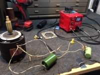
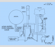
Meanwhile, here is a photo of the wiring and the motor user's manual that shows the wiring schematic. I think I got it correct, but maybe I am missing something.
Here is the current measurements:
1. Both caps measured to spec: 1uF and 2uF.
2. Here are the measurements of the motor terminals. 2 sets of measurements.
Using the continuity function on the VOM, here are the results:
black - blue: UL (unlimited)
black - orange/green: UL (unlimited)
blue - orange/green: 227 ohms
Then, measuring the resistance using the VOM:
black - blue: 665 ohms
black - orange/green: 427 ohms
blue - orange/green: 227 ohms
Meanwhile, here is a photo of the wiring and the motor user's manual that shows the wiring schematic. I think I got it correct, but maybe I am missing something.
Attachments
A wiring error?So there's no mech issue.
You checked all caps etc, no issues.
What then remains?
Banpuku - please confirm that:
The line voltage is connected across blue and green/orange wires.
The run capacitor is connected across the blue and black wires.
- Status
- This old topic is closed. If you want to reopen this topic, contact a moderator using the "Report Post" button.
- Home
- Source & Line
- Analogue Source
- Help wanted: motor stuck when powered