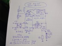
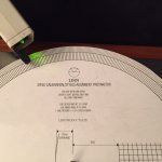
Follow questions rises up to Linn's speedchecker when looking at the circuit diagram (schematic under the first attached image):
1) What is the reason for the not present of Rx, which determine the idle current through the first transistor of the darlington LED driver ?
2) Which task has the connection at the other end of R2 (here is a not connected solder pin provided) ?
3) Why a jumper at R1 to the popsitive rail (Vdd) ?
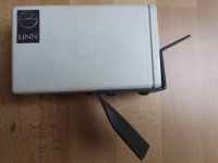
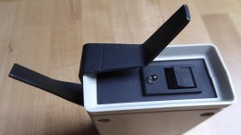
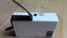
4) From where I can get the genuine enclosure (no longer available from Linn since any years) ?
Best thanks for advices in advance.
1) What is the reason for the not present of Rx, which determine the idle current through the first transistor of the darlington LED driver ?
2) Which task has the connection at the other end of R2 (here is a not connected solder pin provided) ?
3) Why a jumper at R1 to the popsitive rail (Vdd) ?
4) From where I can get the genuine enclosure (no longer available from Linn since any years) ?
Best thanks for advices in advance.
Attachments

Last edited:
Linn — Forum Announcement is death.
Unfortunately also deleted under
Wayback Machine
Additional I try a deep link without success:
Redirect Notice
Maybe someone have saved all topics at his own HDD or server and can upload here.
Unfortunately also deleted under
Wayback Machine
Additional I try a deep link without success:
Redirect Notice
Maybe someone have saved all topics at his own HDD or server and can upload here.
Last edited:
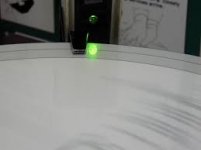
A friend of me is looking for a genuine 300 Hz speed checker für his LP-12. Maybe one of the member know, where it is available in uzsed condition.
Thank you very much.
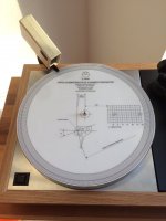
In the attachment two templates for strobe discs (for print) as PDF.
Both 50 Hz and 300 Hz
Thank you very much.
In the attachment two templates for strobe discs (for print) as PDF.
Both 50 Hz and 300 Hz