If my calculation is correct this is the formula of the gain (C2 is ignored)
A(p) = (p*(R3*R4 + R3*R5 + R4*R5)*C1 + R4) / (p*(R3*R5 * R4*R5)*C1 + R5)
Where p = 2*pi*f*j (j is imaginary one or sqrt(-1))
So there are two imoprtant frequencies: one pole and one zero
Pole freq is 1 / (2 * pi * Re1 * C1)
Zero freq is 1 / (2 * pi * Re2 * C1)
Where:
Re1 = (R3+R4)
Re2 = (R3*R4+R3*R5+R4*R5)/R4
A few month later and I'm still trying top wrap my head around this 😀
So I tried to understand the calculation you provided put I really struggle with the term j (imaginary one or sqrt(-1)). How does that translate into a number I can use in my Excel sheet? I tried to google it but was unable to figure it out myself.
Any further explanation would be greatly appreciated!
You need to learn about complex numbers, and how to calculate with them. It is a long time since I used Excel, but it probably has some way of doing complex arithmetic.
Mixi,
ESP RIAA circuit from post 1 is basically National Semiconductor Application note 346 from August 1985. Rod Elliott just placed passive part (HF eq) at the output instead in the middle of the circuit. All necessary calculations for this two stage RIAA eq is in the application note. Use Google to find the application note.
ESP RIAA circuit from post 1 is basically National Semiconductor Application note 346 from August 1985. Rod Elliott just placed passive part (HF eq) at the output instead in the middle of the circuit. All necessary calculations for this two stage RIAA eq is in the application note. Use Google to find the application note.
Excel 2007 and higher have COMPLEX and IMAGINERY functions (I wish I knew it sooner...).You need to learn about complex numbers, and how to calculate with them. It is a long time since I used Excel, but it probably has some way of doing complex arithmetic.
I recently set about analysing the same circuit configuration in an old pre-amp design that I built about 25 years ago and which I have been resurrecting along with my old turntable.
Complex numbers using the j notation are used to express impedances that consist of resistive and reactive components. An impedance is expressed as R + jX where R is resistance and X is reactance. See Electrical impedance - Wikipedia
In order to calculate the impedances in the transfer function, you need to get the expressions into the form R + jX. These can then be manipulated using Excel functions.
I think there is a small error in the transfer function quoted, which I believe should be:
A(p) = (p*(R3*R4 + R3*R5 + R4*R5)*C1 + R4 + R5)/ (p*(R3*R5 + R4*R5)*C1 + R5)
The RIAA time constants are:
Pole (3180µs) = C1*(R3 + R4)
Zero (318µs) = C1*(R3*R5 + R4*R5 + R3*R4)/ (R4 + R5)
To calculate the time constants, you don’t need to worry about the j term.
Putting the transfer function expressions into the complex number form:
A(p) = (R4+R5+j*2*pi*f *C1*( R3*R4 + R3*R5 + R4*R5))/ (R5 + j*2*pi*f *C1*(R3*R5 + R4*R5))
The transfer function can then be entered in excel as:
=IMABS(COMPLEX(R_4+R_5,2*PI()*F*C_1*(R_3*R_4+R_3*R_5+R_4*R_5)))/IMABS(COMPLEX(R_5,2*PI()*F*C_1*(R_3*R_5+_R4*R_5)))
The COMPLEX function is used to define the complex number expressing the impedance. The IMABS function is used to calculate the magnitude of the impedance.
This will allow you to plot the transfer function for frequency F.
Convert the result into dB:
= 20*LOG10(A(p))
and plot the horizontal frequency axis as a log scale.
To get the whole RIAA transfer function of the circuit, you then need to add the 75µs pole.
Thanks, for all the contributions.
The quoted application note is indeed very helpful. Answers a lot of questions and raises a few new ones 🙂
I'm struggling a bit with the passive filter part. Rod Elliott uses an RC filter to roll of at 2100Hz and another CR filter to roll of around 1Hz. As far as I unterstand it the CR filter is only there to block DC from the following stage.
Now the application note design also uses two filters in a row, right? The RC (r3, c3) rolls off at roughly 2100Hz and the CR (c4, r6) rolls off at roughly 1Hz. So far, so good. But if the CR filter is only there to block DC, shouldn't is be after the second gain stage? Or is it there to give the option of implementing the IEC Amendment? Equation 5 and the text below point in this direction.
Also what confuses me is the sentence "while the 2122 Hz rolloff is accomplished by the passive network R3, R6, and C3". Isn't it really just R3, C3 taking care of that rolloff?
The RIAA time constants are:
Pole (3180µs) = C1*(R3 + R4)
Zero (318µs) = C1*(R3*R5 + R4*R5 + R3*R4)/ (R4 + R5)
To calculate the time constants, you don’t need to worry about the j term.
So I'm trying to understand this piece by piece.
If I use the above formulae with the values R3=10k, R4=180k, R5=4,7k, C1=22uF, I get Pole= 0,00418 and Zero=0,00403. Both numbers don't really make sense, do they? Or am I doing something wrong?
I got 4.18s for the pole, so something is wrong. First, 22uF looks rather large for an RIAA network component. Second, your answer and mine are a factor of 1000 apart. Maybe the 22uF should be 22nF? Then I get 4180us, which at least is in the right ballpark.
you're obviously right - it's 22nf.
if now you change the 180k resistor to 130k - as suggested by the designer in a revision - you should get 3080us which is close enough i guess.
if now you change the 180k resistor to 130k - as suggested by the designer in a revision - you should get 3080us which is close enough i guess.
...on another forum people seemed to have complained about excess woofer movement...
Read #06: ..vigorous movement of the woofer cones even when there is no bass content. If this is an issue with your setup, I recommend that you include a Project 99 subsonic filter.
A well-damped subsonic filter has some loss at 50Hz. Rod has fudged the RIAA from 50 to 40Hz to give a slight rise to compensate. Rod does not actually "mandate" you use a subsonic filter. I have never seen a system which did not benefit from getting the subsonics out.
As presented, the plan is very flat except the deliberate rise below 50Hz.
If you prefer to listen to subsonics not present in the master tape/mix, then yes you change 180k to about 135k to hit the prescribed curve.
you're obviously right - it's 22nf.
if now you change the 180k resistor to 130k - as suggested by the designer in a revision - you should get 3080us which is close enough i guess.
Yes, C1=22nF and with R4 = 130k you should then get:
Pole = 3080µs which is 51.7Hz
Zero = 320µs which is 498Hz
With R4 = 180k, the pole was 4180µs which is not very accurate.
Read #06: ..vigorous movement of the woofer cones even when there is no bass content. If this is an issue with your setup, I recommend that you include a Project 99 subsonic filter.
A well-damped subsonic filter has some loss at 50Hz. Rod has fudged the RIAA from 50 to 40Hz to give a slight rise to compensate. Rod does not actually "mandate" you use a subsonic filter. I have never seen a system which did not benefit from getting the subsonics out.
As presented, the plan is very flat except the deliberate rise below 50Hz.
If you prefer to listen to subsonics not present in the master tape/mix, then yes you change 180k to about 135k to hit the prescribed curve.
so what you're saying is:
best to use P06 with P99 (subsonic filter) as intended by the designer.
if used without the subsonic filter, the version with the 135k (instead of 180k) would be the more accurate RIAA option. right?
I'm still trying to fully understand this subject. I have made some progress - especially by studying the recommended Application Note which gives a detailed description on how to calculate the values for a hybrid (active/passive) RIAA Network.
It's actually pretty much straightforward. Using the names from Rod Elliotts P06 it works like this:
Choose R4: 133k (as discussed earlier)
Choose voltage gain of first stage: 3,1767 (odd number, but works for the calculation)
Calculate C1 from: 0,00318/R4 = 24n (22n according to Rod Elliott)
Calculate R5 from: 10*R4/(9*9,898*Gain) = 47k
Calculate R3 from: (R4/9)-R5 = 10k
I have verified this calculation for a few networks that I found on the net:
- Rod Elliott P06
- T Phnom Mk II
- An Excel Sheet from hifisonix
- The network presented Application Note 346
The calculation seems to work. BUT .....
....As suggested earlier in post #2 The Pole and Zero can be calculated as follows:
Pole freq is 1 / (2 * pi * Re1 * C1)
Zero freq is 1 / (2 * pi * Re2 * C1)
Where:
Re1 = (R3+R4)
Re2 = (R3*R4+R3*R5+R4*R5)/R4
This was later amended in post #25 to:
Re1 = (R3 + R4)
Re2 = (R3*R5 + R4*R5 + R3*R4)/ (R4 + R5)
I think post #25 is correct.
The thing is..... if I calculate the networks as described above, the Pole / Zero Frequencies never end up where they are supposed to be (50 Hz and 500 Hz). All the networks result in Pole around 45Hz and Zero around 450Hz, which is obviously to low.
Can anyone explain why this happens? Either the calculations are wrong or it's not possible to adjust the RIAA Network according to the ideal Pole / Zero frequencies.
Small deviations from ideal RIAA curve are inevitable if you choose some reasonably simple topology, meaning not too complicated, not too many parts, not needing precise value parts, etc. Since room acoustics will anyhow degrade performance of any audio circuit for 10 or more dBs, there is no point in building anything that requires fanatical precision. Original RIAA eq was conceived for achieving approximate curve with small number of parts and in an easy way. Important word is "approximate". P06 deviation of 0,5dB is more than good enough.
Sure this is more about me trying to understand the whole thing than trying to achieve acoustic perfection.
I'd just really like to understand why it seems that one can either calculate the right Zero/Pole frequencies OR the correct RIAA - when actually they should go together.
I'd just really like to understand why it seems that one can either calculate the right Zero/Pole frequencies OR the correct RIAA - when actually they should go together.
I think the problem is you are using the Baxandall design process from one circuit configuration, which is the same as that used in the AN346 application note, and then calculating time constants using equations derived for the ESP design which uses a different circuit configuration (different RC arrangement in the feedback network).
For the Baxandall/ AN346 circuit the time constants are:
Pole (3180µs) = C1*R4
Zero (318µs) = C1*R4 *(R5 + R3)/ (R5+ R4 + R3)
For the Baxandall/ AN346 circuit the time constants are:
Pole (3180µs) = C1*R4
Zero (318µs) = C1*R4 *(R5 + R3)/ (R5+ R4 + R3)
another calculation question - this time a filter taken from the hagerman bugle circuit. here's a drawing of two filters. What's the one on the right (?)called? Interestingly if the resistors in the two filters have the same resistance (R1 on the left = R1+R2 on the right), the rolloff will be the same. But - according to spice simulation - the filter on the right will "stop" the roll off at some point. I guess that's what you call a zero?
Can somebody tell me the name of the filter on the right?
Can somebody tell me the name of the filter on the right?
Attachments
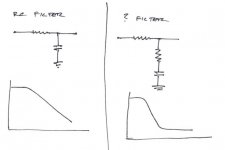
The one on the right is sometimes known as a lead-lag network, especially if it is used to control stability in a feedback loop.
Its tehcnially a lag compensator. Lead compensators have the pole higher in frequency than the zero, and lead-lag compensators involve both a lead and a lag compensator (2 zeroes, 2 poles), apparently.
Poles are always bumps in the graph, and zeroes are dips, so yes the roll off begins at the pole, and stops at the zero. The DC response is unity, and limit at high frequency is set by the ratio of resistors.
Poles are always bumps in the graph, and zeroes are dips, so yes the roll off begins at the pole, and stops at the zero. The DC response is unity, and limit at high frequency is set by the ratio of resistors.
- Home
- Source & Line
- Analogue Source
- RIAA calculation help needed