I've started this thread to explore some issues that came up on another thread recently that were starting to drag that thread in the wrong direction. Hopefully I'll get time to pull in stuff on some other discussions here, but the drive here is to discuss things that would cause non-linear behaviour in cartridges, how to measure that and if anything can be done about it.
The starter for 10 is the conjecture that cartridge frequency response is not independent of program level. This is a contentious issue, not least because there is almost no discussion of this in the literature from the day one way or another.
More to follow...
The starter for 10 is the conjecture that cartridge frequency response is not independent of program level. This is a contentious issue, not least because there is almost no discussion of this in the literature from the day one way or another.
More to follow...
At any given playback level, a cartridge's overall 'f-response' comprises a composite of several separate component parts. Electromagnetic generator (typically hf loss/roll-off), a mechanical 'top' resonant system (centred 8kHz-30kHz) that sometimes props up generator hf roll-off, an electrical resonant LCR impedance system (10-20kHz) that also sometimes props up generator roll-off system in MM/MI carts, and a lf spring-mass elastomer system. There's also a contribution from geometric thd and mistracing distortion that can influence f-response somewhat. And other contributing elements besides.
When combined, the result is the well-known f response curve: lf peak, mid-dip, resonant peak and hf roll-off. Nominally +3dB/-1dB at normal test levels. However, each of the component parts has losses and non-linearities which are level sensitive, and many of them slew-rate sensitive as to losses. It's slew-rate, rather than 'frequency' per se, which is mostly at issue.
I first encountered significant level-sensitive parameters about 6 years ago in collaboration with David Laloum trying to 'perfectly' terminate MM carts, where cartridge inductive behaviour, and hence the generator (not least LCR resonant f and Q), apparently changed significantly dependant upon test level for some cartridges. Especially for very small signals. I still have the charts from that work, and stand by that it is very probably real and a part of vinyl sound.
Exploration of theoretical loss mechanisms in each of the contributing elements to f-response reveals many and various level-sensitive non-linearities. Some are slew-rate specific, or displacement specific. Some increase with level, some decrease.
One might surmise the overall result is probably a level-dependent series of contours of f-response, typically within a bracket of +/- 3dB at the mid-dip, over the decades of normal playback level range where the most audible effects happen. AFAIK there is no single test record to confirm.
IMO the audible result is probably then a big part of vinyl sound - certainly something one doesn't get from digital sources, and only to an extent from tape.
LD
Although hard to find the measurements from the parts of that work that were published are still up at vinylEngine. As per in the mechanical resonance thread I won't post them over here unless LD requests as some of the thinking has perhaps been overtaken, but I will pick some choice FR response plots to look at to trying to unpick these.
And just in case anyone asks 'why MM'. MC carts will have a number of the same issues, but I've started looking at MMs in a new light when I realised that, in many respects I took a step backwards when I dumped my P77 for my first MC. MM offers a number of possibly advantages, not least that you can easily change stylus and this ability to chop and change and experiment makes (for me) a lot of fun. It doesn't actually worry me if I end up discovering I prefer my MCs but I hope to learn a lot.
And just in case anyone asks 'why MM'. MC carts will have a number of the same issues, but I've started looking at MMs in a new light when I realised that, in many respects I took a step backwards when I dumped my P77 for my first MC. MM offers a number of possibly advantages, not least that you can easily change stylus and this ability to chop and change and experiment makes (for me) a lot of fun. It doesn't actually worry me if I end up discovering I prefer my MCs but I hope to learn a lot.
I should note at this point that, as my system is more or less DIY end to end I don't see why I should have to follow things like 47k loading for a cartridge. I can do what I want if the end result is a more accurate reproduction. Just so you are aware ")
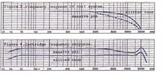
Moving on: Up for discussion is the attached snip from an ortofon brochure for the 520 series from around 40 years ago. This was the first appearance of the split pin generator that Ortofon still use to this day. The claim is eddy current reduction. There is a comparion between solid and split pins. Ortofon use B&K plotters set at 50dB scale for all their other FR measurements, so safe to assume 1dB per division. This does show the classic mid-range dip that some cartridges have. Why this is interesting is that you can still get new cartridges with both pole pin constructions in the OM and superOM ranges and the stylii are interchangeable allowing some testing to be done. And testing is needed as we immediately run into the first problem which was discussed at length in the mechanical resonance thread* here mechanical resonance in MMs, which came to a grinding halt mainly due to my inability to complete a test board. However George did build a unit and came up with some interesting data using a Shure M97.
If you look at the work of Hans van Maanen and the very interesting Steven Van Raalte paper from Linear Audio volume 3 you can see that it is possible to assemble a combined electrical/mechanical resonance response that produces the response curve that ortofon show. However I immediately see something I don't like as this requires a 13dB lift from mechanical resonance at 21kHz. 3-4dB I could believe, but 13 is a lot. The 13dB figure you can see is the same between the VR paper and the ortofon graphs. If you look here mechanical resonance in MMs, there is the transmission line model LD has worked on that does show the possibility of this sort of level of enhancement. I still don't like it as that infers an exceedingly undamped setup.
So we need some measurements that try to isolate cartridge response from cantilever. mechanical resonance in MMs shows a measurement of the ortofon solid pin generator using a transimpedance circuit LD designed and build and I have a variant waiting for me to get off the internet and build. With a loading scheme that puts cartridge electrical resonance out the picture you can see that you get a flat response within a gnatfart across the audio band**. There is a rising response indicating something, possibly mechanical, but it's not anywhere near that you would expect cw vR or ortofon.
Overall I am not sure the generally accepted cartridge electrical model is correct! But I have probably missed something as usual. If we are to explore losses in the generator, we need to make sure we have a half decent generator model to start with?
*I will x-ref that thread but don't want to copy wholesale chunks out of context. Sorry if that means you have to have several tabs open. It's worth it.
**LD will need to explain if he had any additional corrections in place to get this response.
Moving on: Up for discussion is the attached snip from an ortofon brochure for the 520 series from around 40 years ago. This was the first appearance of the split pin generator that Ortofon still use to this day. The claim is eddy current reduction. There is a comparion between solid and split pins. Ortofon use B&K plotters set at 50dB scale for all their other FR measurements, so safe to assume 1dB per division. This does show the classic mid-range dip that some cartridges have. Why this is interesting is that you can still get new cartridges with both pole pin constructions in the OM and superOM ranges and the stylii are interchangeable allowing some testing to be done. And testing is needed as we immediately run into the first problem which was discussed at length in the mechanical resonance thread* here mechanical resonance in MMs, which came to a grinding halt mainly due to my inability to complete a test board. However George did build a unit and came up with some interesting data using a Shure M97.
If you look at the work of Hans van Maanen and the very interesting Steven Van Raalte paper from Linear Audio volume 3 you can see that it is possible to assemble a combined electrical/mechanical resonance response that produces the response curve that ortofon show. However I immediately see something I don't like as this requires a 13dB lift from mechanical resonance at 21kHz. 3-4dB I could believe, but 13 is a lot. The 13dB figure you can see is the same between the VR paper and the ortofon graphs. If you look here mechanical resonance in MMs, there is the transmission line model LD has worked on that does show the possibility of this sort of level of enhancement. I still don't like it as that infers an exceedingly undamped setup.
So we need some measurements that try to isolate cartridge response from cantilever. mechanical resonance in MMs shows a measurement of the ortofon solid pin generator using a transimpedance circuit LD designed and build and I have a variant waiting for me to get off the internet and build. With a loading scheme that puts cartridge electrical resonance out the picture you can see that you get a flat response within a gnatfart across the audio band**. There is a rising response indicating something, possibly mechanical, but it's not anywhere near that you would expect cw vR or ortofon.
Overall I am not sure the generally accepted cartridge electrical model is correct! But I have probably missed something as usual
. If we are to explore losses in the generator, we need to make sure we have a half decent generator model to start with? *I will x-ref that thread but don't want to copy wholesale chunks out of context. Sorry if that means you have to have several tabs open. It's worth it.
**LD will need to explain if he had any additional corrections in place to get this response.
Attachments
Still no data, guys? Graphs with no scales? No test conditions, specific groove velocities (there had to be more than one), cartridge and load used?
I'm not doubting the theory here, but how much of a problem is it?
@billshurv - I discovered 40 years ago that all carts don't all work well with 47K/200pf termination. At the studio where I worked then we build up cart termination boxes with pots to alter the R and variable capacitors to vary C to flatten off cart response. Used a paper-based tracking response plotter and a test record with recorded 20-20K log sweep recorded without RIAA. That was in the days of preamps with reactive inputs and carts like the Shure V15-III. It was kind of a mess, but the term box fixed a lot of it. We moved to a preamp with completely non-reactive input and an purely resistive load with and adjustable purely C load. Used to use a C meter on the cabling so we know what it was.
We're just starting out on this thread and setting the scene. Sorry if it's not going fast enough for you but I have a full time job and a baby who isn't sleeping well due to a chest infection.
Personally I don't yet know the scale, that's what we need to find out. One step at a time.
Personally I don't yet know the scale, that's what we need to find out. One step at a time.
If you mean posts by LD, he will have supporting data. I am trying to find some of the stuff that survived the purge on this to see if there is anything useful. Just because a graph hasn't been posted doesn't mean one doesn't exist. If you followed the links in my long post you will see plenty of graphs. They just don't need repeating here.
But this will be a (possibly long) process of discovery.
But this will be a (possibly long) process of discovery.
If you mean posts by LD, he will have supporting data. I am trying to find some of the stuff that survived the purge on this to see if there is anything useful. Just because a graph hasn't been posted doesn't mean one doesn't exist. If you followed the links in my long post you will see plenty of graphs. They just don't need repeating here.
But this will be a (possibly long) process of discovery.
You linked to a thread with hundreds of posts. I started with a few, it was all about resonances. How about at least linking to something about this dynamic behavior, or the graphs you speak of? I'm not up for reading that thread. It seems to be about stiff that is already known, and being re-discovered.
Indeed, opportunity certainly is out there.I don't see why I should have to follow things like 47k loading for a cartridge. I can do what I want if the end result is a more accurate reproduction.
Well, thanks to you, the advanced position on having multiple transimpedance loaded preamps available should make this thread very interesting I think.Moving on: Up for discussion is the attached snip from an ortofon brochure for the 520 series from around 40 years ago. This was the first appearance of the split pin generator that Ortofon still use to this day. The claim is eddy current reduction. There is a comparion between solid and split pins. Ortofon use B&K plotters set at 50dB scale for all their other FR measurements, so safe to assume 1dB per division. This does show the classic mid-range dip that some cartridges have. Why this is interesting is that you can still get new cartridges with both pole pin constructions in the OM and superOM ranges and the stylii are interchangeable allowing some testing to be done. And testing is needed as we immediately run into the first problem which was discussed at length in the mechanical resonance thread* here mechanical resonance in MMs, which came to a grinding halt mainly due to my inability to complete a test board. However George did build a unit and came up with some interesting data using a Shure M97.
TI loading eliminates the LCR resonance, and so makes for far easier analysis of f response and other methods when looking at contributions from mechanics and magnetics.
Transverse mechanical TL models are probably best for cantilevers, IMO. As it stands the model is quite basic and just shows the correct form surprisingly easily. Bending losses can be slew rate and displacement sensitive, BTW.If you look here mechanical resonance in MMs, there is the transmission line model LD has worked on that does show the possibility of this sort of level of enhancement. I still don't like it as that infers an exceedingly undamped setup.
In developing the model sufficiently to include real behaviour of bending losses, we'll pretty much end up understanding what really goes on with cantilevers and settle a few myths along the way I suspect.
The way I approached this in the past was to examine coil losses as a 2-port network looking into the pins of the coil. i.e to investigate non-ideal inductive behaviour as an electrical coil, and see how that varied with level. Especially for small signals, there's not much existing material on it. I got as far as verifying significant changes to electrical impedance with level for small signals.So we need some measurements that try to isolate cartridge response from cantilever.
Yes, I assume the rising response is due to top mechanical resonance. And the Aurak TI preamp used was as per the schematic, no fudges.billshurv;5371289[URL="http://www.diyaudio.com/forums/analogue-source/303389-mechanical-resonance-mms-post5008802.html" said:mechanical resonance in MMs[/URL] shows a measurement of the ortofon solid pin generator using a transimpedance circuit LD designed and build and I have a variant waiting for me to get off the internet and build. With a loading scheme that puts cartridge electrical resonance out the picture you can see that you get a flat response within a gnatfart across the audio band**. There is a rising response indicating something, possibly mechanical, but it's not anywhere near that you would expect cw vR or ortofon.
I agree, the accepted model isn't complete, and fixing that will probably be a good place to start.Overall I am not sure the generally accepted cartridge electrical model is correct! But I have probably missed something as usual
No additional corrections, and level was 1.2cm/s lateral at 1kHz with some break at 10kHz, spot frequency sine tones.**LD will need to explain if he had any additional corrections in place to get this response.
LD
You linked to a thread with hundreds of posts. I started with a few, it was all about resonances. How about at least linking to something about this dynamic behavior, or the graphs you speak of? I'm not up for reading that thread. It seems to be about stiff that is already known, and being re-discovered.
I linked to specific posts that contained useful information. Yes, stuff is being rediscovered, but if you look at the number of shure technical papers, and AES papers where concepts were accepted that don't stand scrutiny.
In this case I was making the point that, if you need 10-13dB of resonant boost at 20kHz from the stylus assembly, a transimpedance loaded cartridge would be 10-13dB up at 20kHz. It's not, its 1-2dB up. A comparative measurement on a Shure M97xe showed similar. Therefore something is fishy with the simple LRC model of a cartridge and the preamp loading. Something worth of investigation as part of working out how we proceed to find out more about dynamic effects.
Once the penicillin takes effect I should have the few hours needed to get my transamp working then we will have 3 that members here have to do testing on. What I am missing is a test record with different levels on, but still looking around for something suitable.
Indeed. I'm not aware of one, but do have an independent look. Persuading the test record thread to re-up the suggested level sweep tests might be the best prospect?What I am missing is a test record with different levels on, but still looking around for something suitable.
LD
...And there's the real elephant in the room. No actual tests have ever been made of this so-called dynamic response issue because the only available test records have only sweeps at 0db re: 3.54cm Per Second or -14dB with RIAA record EQ.
I wonder when they'll discover the problem with cutting multiple level sweeps on a test record. Probably will have to talk to an actual lathe operator for that one. Hopefully someone figures out this can't be done with RIAA eq on all the sweeps if you really want to cover the full DR, or want accurate FR.
I wonder when they'll discover the problem with cutting multiple level sweeps on a test record. Probably will have to talk to an actual lathe operator for that one. Hopefully someone figures out this can't be done with RIAA eq on all the sweeps if you really want to cover the full DR, or want accurate FR.
That's untrue. a) Different test records have different test levels, especially pink/white noise tracks. This correlates well with observed deviation in response for some cartridges, as though deviation and level are correlated variables b) loss mechanisms have been characterised in cartridge coils as a 2-port network.No actual tests have ever been made of this so-called dynamic response issue
On the contrary, it's been an historical assumption that f response is independent of level. Unless one has curiosity enough about loose ends, join the dots or think about theoretical non-ideals, apparently it's gone unchallenged. But an assumption it is, and not a safe one. For good reasons.
Nature is full of such non-linearities and loss mechanisms. Ears. Microphones (they grow on Decca trees
)Obviously. So turn RIAA off, limit the f range to levels supported. Not all level contours can be full spectrum in vinyl playback.Hopefully someone figures out this can't be done with RIAA eq on all the sweeps if you really want to cover the full DR, or want accurate FR.
LD
Last edited:
I missed the link to George's measurements on the lowly Shure M97. They can be found here mechanical resonance in MMs . (at least assuming my ability to x-ref works). Now there comparing traditional 47k loading with trans loading you can see approximately 4dB difference at the top end. Now the shure is fairly massive assembly so one might expect they Engineered in some 'help' from the resonances, but a far cry from the circa 13dB you might expect from some sources.
So for me a good working assumption is that there is 2-4dB peaking at 20kHz that may be caused by the mechanical system, ready to be shot down as more data appears.
I should note, for experimental purposes and, if you can take a small noise hit you can take out the HF pole in RIAA and load the cartridge down to give that roll off for free.
I've been doing a little bit of messing around with numbers to see if I can find a starting mechanical model and right now all I can work out is that most people have a LOT more capacitance than they think. Work in progress....
- Status
- This old topic is closed. If you want to reopen this topic, contact a moderator using the "Report Post" button.
- Home
- Source & Line
- Analogue Source
- Cartridge dynamic behaviour