Need to find the source or date the record was made. The classic test records mostly predate digital test sources. It would have been a GR noise generator which are quite random and stable. One issue would be the compressor in the cutting chain affecting the HF part of the spectrum.
In case it was not clear the cutterheads have a 20 dB resonance between 1 and 2 KHz. Feedback is used to control that but the mechanicals are still reacting.
In case it was not clear the cutterheads have a 20 dB resonance between 1 and 2 KHz. Feedback is used to control that but the mechanicals are still reacting.
All I know is that my two test records don't show this.
HFS-75 was probably analog, considering the financial and technical capabilities of the magazine and record studios in the UK.
GR equipment was rare in the UK
My Elipson is much more recent and likely to be PC digital
The dubious sources would be early digital made with a too short pseudo random sequence generator. You used to see this sort of design in "circuit ideas" letters in the electronics magazines in the 70s and 80s. Few people had access to FFT in those days to detect the artifacts.
Vibration of real objects is different from electronic resonances that most people are schooled with. Rather than a simple transfer of stored energy from one form to another, energy is stored in a bending tension that propagates within the body. A closer electrical analogy is a transmission line.
Real objects bend and propagate vibration in degrees of freedom depending on their shape and support. The outcome in response to an f sweep of stimulus is a series of resonant modes that depend on the phase velocity of bending propagation within the body, compounded by impedance discontinuities. Really, mechanical impedance changes with frequency in a series of peaks and troughs, analogous to an electrical transmission line though that has only one dimension. The modes tend to be widely spaced in the f domain for simple vibration and objects.
So here it looks like something in the cutter process such as the cutter head, or lathe platter, vibrates in a relatively simple way. Then one ends up with a series of resonant peaks in the f domain corresponding to impedance troughs where the body is easy to bend.
It doesn't look electronic in origin to me, mostly because it doesn't show up on the left channel. That said, the pink noise doesn't look too ideal but it seldom does in test records for whatever reason. Maybe that is linked?
LD
Last edited:
Aside: capacitors are really 2D transmission lines: if one has fast enough test and measurement gear, one can see resonant modes arising from reflections at edges of say foil plates...…analogous to an electrical transmission line though that has only one dimension.
LD
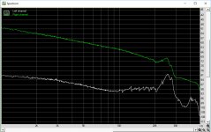
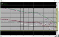
The first two Images recorded with pink noise from the same Adjust+ LP that Scott used, both 33 1/3 rpm.
First image: stereo, both channels from 20Hz - 20khz,
Second image: one channel pink noise, from 1kHz to 48kHz.
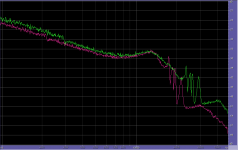
And to compare, the third image is the merger of Scott's image with mine, both brought to exactly the same scale and the same level.
The most prominent is the peak in the crosstalk signal between 20kHz and 30kHz, being exactly the same for both, white vs purple.
Since this peak shifts upwards in frequency when going to 45rpm, this is part of the record and not caused by the Cart.
Hans
First image: stereo, both channels from 20Hz - 20khz,
Second image: one channel pink noise, from 1kHz to 48kHz.
And to compare, the third image is the merger of Scott's image with mine, both brought to exactly the same scale and the same level.
The most prominent is the peak in the crosstalk signal between 20kHz and 30kHz, being exactly the same for both, white vs purple.
Since this peak shifts upwards in frequency when going to 45rpm, this is part of the record and not caused by the Cart.
Hans
Attachments

We need to be careful to include stylus geometry/groove interface issues with things that will scale with RPM. I'm assuming the 35% increase in RPM will change the tracing error a fairly minor amount? I have more disks to try including the CBS Labs ones, these certainly predate digital processing. Typical analog pink noise generators used an RC ladder filter on white noise from a broadband generator like an avalanche diode or zener, there are no mechanisms in that process that I know of to make such abrupt frequency response aberrations.
BTW the first one was the Telarc Omnidisk all early digital.
BTW the first one was the Telarc Omnidisk all early digital.
Scott, the CBS up to 50kHz track is sinusoid freq sweep or pink noise?
George
Constant velocity sine, I should check (my old plots) there are L and R only to do the crosstalk at the same time. Right now I am not set up for doing the non-RIAA LP's. Thanks to Jan I have a 45 RPM pink noise "single" , only L+R but I can try the reverse 45 to 33.33 experiment.
Scott, what exactly do you mean with the above ?We need to be careful to include stylus geometry/groove interface issues with things that will scale with RPM.
Isn't scaling the rpm not just an excellent way to separate Cart anomalies from LP "contamination".
And does MC versus MM, when using the same LP, not help to get more insight in the differences between both and thereby possibly in the dynamic behaviour of the MM ?
That this MM's FR has been lifted in magnitude between 10k and 20k for both speeds and the MC's FR not, is telling something about the used MM, true ?
Hans
Scott, what exactly do you mean with the above ?
The stylus tracing the groove i.e. distortion has to track the groove. That is running a 1k tone becomes a 1.35k tone and the harmonics have to be at multiples of 1.35k whether they are in the groove or from the tracing distortion of the stylus. By tracing I'm talking purely the geometric issues and not the additional confounders due acceleration and other dynamic issues. A high Q resonance at 1k is not excited by a 1.35k signal.
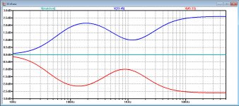
Here is a well behaved one, CH Precision, a 7" 45, heavy vinyl. The label says 250 - 30kHz and the high end is brickwalled at 30kHz so I assume it is digitally generated. Same cart/setup as all the other measurements, Mmy rule is I have an existence proof of a pink noise LP that behaves as expected so there is something wrong with all the others. Factoring out the RIAA and RPM these lie on top of each other.
Attachments

Last edited:
Maybe the brickwalling is preventing an aliasing nasty from the cutter digital delay line?
I don't follow, the CBS Labs LP was mastered in the 60's with no digital anything.
Not even preview. Since its all.predictable they ran fixed pitch and manually went through the test sequence. No automation and vintage GR test sources, mostly tube.
Not even preview. Since its all.predictable they ran fixed pitch and manually went through the test sequence. No automation and vintage GR test sources, mostly tube.
I suspect many of these old test LP's were full of artifacts that fell through the cracks. It would be interesting to find out what CH Precision did, it seems very clean at 45RPM well beyond 20kHz.
Last edited:
Actually designing a circuit that caused the CBS artifacts without some sort of delay line cancellation would be hard. Analog delay lines have been around a long time, but I don't see why CBS would have needed one
Two questions:I suspect many of these old test LP's were full of artifacts that fell through the cracks. It would be interesting to find out what CH Precision did, it seems very clean at 45RPM well beyond 20kHz.
The level of the CBS seems 6 dB higher, could it possibly be your Cart is not able to follow this higher modulation level at HF ?
What exactly are the details of this CH Precision disk, it would be nice if it still could be located somewhere.
Last edited:
Actually designing a circuit that caused the CBS artifacts without some sort of delay line cancellation would be hard. Analog delay lines have been around a long time, but I don't see why CBS would have needed one
Another possibility is some artifact of high frequency limiting. An analog pink noise signal with RIAA preemphasis would need some serious filtering a digital one can be generated with guaranteed no energy >30KHz. The measured problems with several different LP's are quite different and to me look more like chaotic behavior than something simply running out of its linear range.
- Status
- Not open for further replies.
- Home
- Source & Line
- Analogue Source
- Cartridge dynamic behaviour