Does the motor run on the difference between 165Vac and 117Vac? i.e. is it a 48Vac motor?
The switching in the upper half of the pdf seems to be converting the motor from 2pole to 4pole (I doubt it is for 4 pole to 8pole). That is the speed change part and explains why there are so many wires into the motor.
The switching in the upper half of the pdf seems to be converting the motor from 2pole to 4pole (I doubt it is for 4 pole to 8pole). That is the speed change part and explains why there are so many wires into the motor.
My thought was that it uses two voltages , 165 V for higher speed and 117 V for lover. Wouldn't it mean in that case that it is not running on 48 volts? That was why I tried to draw wiring for higher speed (if correct what I have done)... should I try it as such configuration? from schematic it seems that 117 V is disconnected if switching is in upper position ...
voltage does not change speed.
b2 is the ON/OFF switch.
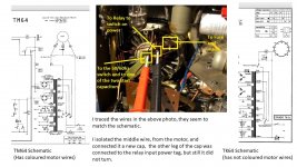
Note there are three wires from the transformer to the motor. The two tappings are labeled 165Vac and 117Vac.
Maybe the 2pole uses motor windings in series and thus needs more voltage to drive the current. Torque is proportional to current.
But when in 4pole mode with windings direct to the supply then adequate torque and current are available from the lower voltage.
I'm not sure how the speed changeover affects the actual internal wiring and the effective impedance.
The speed change appears to be the three pairs of slide switches.
b2 is the ON/OFF switch.
Note there are three wires from the transformer to the motor. The two tappings are labeled 165Vac and 117Vac.
Maybe the 2pole uses motor windings in series and thus needs more voltage to drive the current. Torque is proportional to current.
But when in 4pole mode with windings direct to the supply then adequate torque and current are available from the lower voltage.
I'm not sure how the speed changeover affects the actual internal wiring and the effective impedance.
The speed change appears to be the three pairs of slide switches.
Last edited:
is the tapping 155Vac or 165Vac?
Note that the slide switch connects EITHER 165, OR 117Vac.
remember post3
Note that the slide switch connects EITHER 165, OR 117Vac.
remember post3
I'd guess you have a syncronous motor that locks to mains frequency.
Last edited:
Grundig TK64, PAPST Motor 7882-032 Failure
What a great read ! Hope you all can help me.
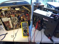
I am restoring a grundig TK64 spent many weekends got it all working, then after 2 hours of running, the motor has ceases to spin any more
I cant find a suitable schematic, as mine has a 50/60 switch, as well as TWO large motor related caps, sandwiched between two chassis plates, almost impossible to get out.
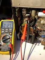
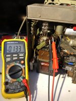
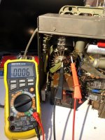
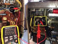
The color coding is very hard to see, one see, if i am guessing it could be red, yellow and green. SEE Photos please.
Seems to have 117-120v across two of poles, and nothing on the 3rd pole, which is where the cap joins in.
I just want it to spin, and am happy to hard wire it up, with a cap, but cant tell the wiring colours so how to do it ? Some others have said one is a start cap and the other is a run cap, as in the TK30. My TK64 schematic only has one cap, but there are two there in the sandwich.
HELP PLEASE... I have fixed all the electronics.
What a great read ! Hope you all can help me.
I am restoring a grundig TK64 spent many weekends got it all working, then after 2 hours of running, the motor has ceases to spin any more
I cant find a suitable schematic, as mine has a 50/60 switch, as well as TWO large motor related caps, sandwiched between two chassis plates, almost impossible to get out.
The color coding is very hard to see, one see, if i am guessing it could be red, yellow and green. SEE Photos please.
Seems to have 117-120v across two of poles, and nothing on the 3rd pole, which is where the cap joins in.
I just want it to spin, and am happy to hard wire it up, with a cap, but cant tell the wiring colours so how to do it ? Some others have said one is a start cap and the other is a run cap, as in the TK30. My TK64 schematic only has one cap, but there are two there in the sandwich.
HELP PLEASE... I have fixed all the electronics.
Attachments
- Status
- This old topic is closed. If you want to reopen this topic, contact a moderator using the "Report Post" button.
- Home
- Source & Line
- Analogue Source
- Grundig PAPST motor...