This is a spin off thread from the Muscovite Mini II phono stage here: The Muscovite Mini II 6N14P Phono Stage
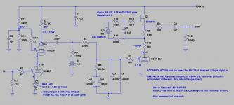
It is essentially very similar to the previous version with a few minor changes and the substitution of a 6N23P (or ECC88/6DJ8/7308) for the 6N14P used in the previous design.
With twice the transconductance, frame grid construction and slightly better linearity the 6N23P gives me about 6dB of additional voltage gain. I think in some ways it sounds better too.
In addition the recommended 6S3P-EV used in the second stage may be replaced with a 5842/417A with the only changes required being wiring with the correct pin out for the 5842.
Refer to the referenced thread for power supply and other details.
Note that the picture shows diodes for bias but I am in fact using LEDs now as shown in the schematic.
Attachments
A couple of days in I have concluded that this is a significant improvement in performance over the 6N14P based design..
I would recommend selecting tubes for the cascode stage that operate in the region of 10mA with a bias LED having a VF of 1.75V or thereabouts.
The inexpensive 6N23P are quite good although I will admit that I have switched to NOS Telefunken E88CC, just a bit nicer overall.
I would recommend selecting tubes for the cascode stage that operate in the region of 10mA with a bias LED having a VF of 1.75V or thereabouts.
The inexpensive 6N23P are quite good although I will admit that I have switched to NOS Telefunken E88CC, just a bit nicer overall.
Nice circuit. Output impedance may be a little high, though. Perhaps a white-cathode-follower for the output if you want to use all tubes. Or wrap a little feedback around?
Also why apply the negative bias to the grid of V2 by a battery? Does it run out quickly? Is there any difference from using a 1.6V LED on the cathode of V2?
Also why apply the negative bias to the grid of V2 by a battery? Does it run out quickly? Is there any difference from using a 1.6V LED on the cathode of V2?
Good questions all..
The output impedance is actually pretty low - in the vicinity of 150 ohms including the build out resistor, it will drive quite capacitive cables without any difficulty. It could be reduced further by adding a resistor or CCS to ground from the source of the mosfet to get the current up - currently it is around 10mA and that results in a transconductance of about 50,000umhos - it increases substantially at higher currents at the price of considerably higher dissipation.
An LED would give good service biasing the second stage, but I actually prefer the battery based grid bias in the second stage; I guess it's a choice as much as anything, and not necessarily a rational one, but I'm having fun and batteries work quite nicely as bias sources. Some claim some DC voltage across the EQ caps is not a bad thing but since I generally use polystyrene or teflon I am doubtful if there is an audible benefit. The AA battery will last many years as there is no discharge path other than the leakage in the EQ caps, the bigger problem is the A23 - I've encountered some with internal discharge paths that were dying after a year, but the Duracell A23 I am currently using seem to last at least a couple of years.
Hmm. If those batteries run down a little faster than usual or fall out of their holders then it will not be doing V2 any good.
Also, why the need for R5? It seems you are just increasing noise, the output impedance from the plate of V1A will be a steady 11-12K once the circuit is powered up, why not use that as the first resistor in your EQ network? You'll be able to remove a component and improve your noise performance.
Also, why the need for R5? It seems you are just increasing noise, the output impedance from the plate of V1A will be a steady 11-12K once the circuit is powered up, why not use that as the first resistor in your EQ network? You'll be able to remove a component and improve your noise performance.
Q1 is a constant current source in addition to its function as a follower, with adequate heatsinking the fet will survive a bias failure- the tube will not see a significant increase in current, and dissipation will decrease with the reduction in plate voltage as the tube saturates..
Note in 10 yrs I have yet to have a bias battery failure.
R5 is chosen as a reasonable compromise between minimizing sensitivity to parametric variations in the first stage, noise, and cap size/quality considerations. Available current and distortion are a consideration too. The overall SNR is dominated by Johnson noise from cartridge and transformer resistance.
Hi,
That's OK if you need the phono pre to drive an amp with a vol ctrl sitting close to the speakers but if you use an active line preamp it's less of a problem, right?
Ah, I'm already dreaming up some circuits using high transconductance valves in parallel to get rid of the step up xfrormer and so on.
Maybe a maxi muscovite, he....
Cheers,")
The output impedance is actually pretty low - in the vicinity of 150 ohms including the build out resistor, it will drive quite capacitive cables without any difficulty.
That's OK if you need the phono pre to drive an amp with a vol ctrl sitting close to the speakers but if you use an active line preamp it's less of a problem, right?
Ah, I'm already dreaming up some circuits using high transconductance valves in parallel to get rid of the step up xfrormer and so on.
Maybe a maxi muscovite, he....
Cheers,
Hi,
It'll be as quiet a pair of squared church mice, trust me.
Cheers,
Today 12:57 AM
piano3 I'm sure you'll have lots of fun getting it hum-free Frank!
It'll be as quiet a pair of squared church mice, trust me.
Cheers,
Well, what happens as the valves age?- the assumption of infinite output in a cascode is only an approximation. Losing the series resistor to decrease noise also means a steep AC loadline for the input stage.
This is quite true and I was not going to get too far into it posting from my cell phone so I will elaborate a bit for Monty.
In fact the rp of this cascode is typically not much north of 100K, and varies rather significantly over the life of the tubes used. As designed quite large variations in rp will have very little effect on the accuracy of the RIAA. For linearity considerations I like EQ loads to be relatively high Z in comparison with the driving source impedance and also because varying load impedance slightly modulates the gain in the first stage and makes achieving good RIAA accuracy more difficult. Gain in the first stage is 40dB so signal amplitudes are quite healthy at the input to the RIAA network..
Hi,
That's OK if you need the phono pre to drive an amp with a vol ctrl sitting close to the speakers but if you use an active line preamp it's less of a problem, right?
Ah, I'm already dreaming up some circuits using high transconductance valves in parallel to get rid of the step up xfrormer and so on.
Maybe a maxi muscovite, he....
Cheers,
This phono stage is actually a 2.5 meter run of cable away from the line stage input as it is used with my second table on a separate rack on the other side of the built in record cabinet. I also had a really bad experience years ago when I designed a nice sounding budget phono stage with a source Z of about 10K.. In listening tests the reviewer ignored my advice about using low capacitance cable and used a cable from MIT known to be extremely capacitive. The results were not good, and as a result the unit did not get dealer distribution. I've learned my lesson - all my current designs have low output impedance as a result.
I guess at some point we should work on that head amp we've been discussing for a year. I suspect there is an ideal Russian tube...
Split of the new high gain MC phono pre design to this thread: http://www.diyaudio.com/forums/anal...beration-high-gain-tube-mc-phono-pre-amp.html
Very poor PSRR, but I am very good at PSU design so not much of an issue, the high gain and very low miller capacitance are VERY attractive.
Some time ago I started to suspect that even LOMC driving transformers were more sensitive to load capacitance than I had been led to believe. 400pf reflected to the primary of a 1:16 SUT looks like 0.1uF which is a substantial amount of capacitance.
Typical previous solutions I tried with gyrator loaded triode connected D3A resulted in miller capacitance of up to 400pF and this did not exclude strays from wiring or the lead in cables. Clearly excessive, and audible. Yes PSRR was great. The capacitance was high enough to preclude the use of most MM cartridges, and really the best match would be a HOMC which would not have trouble driving the capacitance. (But I have a personal preference for LOMC with transformers)
This design was the evolution of several prior designs including one that utilized the 6J9 (Russian) pentode in the front end. I didn't like the way it sounded even though the measurements were fairly decent. (1/f noise was a bit of a problem too)
Hi Michael,
I typically use a single alkaline AA cell per channel, but nominally 1.5V coin cells or AAA batteries will also work fine.
Battery life should be rated shelf life of the cell, but I usually replace them every couple of years.
I generally use CPC connectors, but a variety of other connectors are fine provided they are safe for the 300V plate voltage.
The power supply design is in another one of the threads and is fairly critical to the performance of the design. One of Salas SSHV supplies could make a good substitute if the idea of a tube based supply is too daunting.
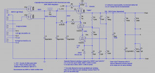
For those who don't know it the power supply and filament supply for the Muscovite Mini II are exactly the same as I used in the Muscovite Mini. I recommend a stereo supply as I implemented.
Here is a revised schematic showing what I did in this supply with the exception that I have two separate filament windings for the 6W6GT pass tubes.
Note that only a single power transformer and rectifier is required and two is probably beyond the realm of reason for this design.
The filament regulator is one of the dc regulators advertised on eBay as having a 40uV output noise performance. Probably not that good, but it is good - well under 1mV - I measured 200uVpp on one of mine. This is quiet enough I think. I used a 50VA 9V toroid and a conventional bridge rectifier into a 22000uF 25V electrolytic and directly into the regulator. The supply is floating, but not elevated. There is a pair of 330 ohm 1/2W resistors to audio ground (potential divider).
Attachments
For those who don't know it the power supply and filament supply for the Muscovite Mini II are exactly the same as I used in the Muscovite Mini. I recommend a stereo supply as I implemented.
Here is a revised schematic showing what I did in this supply with the exception that I have two separate filament windings for the 6W6GT pass tubes.
Note that only a single power transformer and rectifier is required and two is probably beyond the realm of reason for this design.
The filament regulator is one of the dc regulators advertised on eBay as having a 40uV output noise performance. Probably not that good, but it is good - well under 1mV - I measured 200uVpp on one of mine. This is quiet enough I think. I used a 50VA 9V toroid and a conventional bridge rectifier into a 22000uF 25V electrolytic and directly into the regulator. The supply is floating, but not elevated. There is a pair of 330 ohm 1/2W resistors to audio ground (potential divider).
Do you make a PCB of HV regulator?
- Status
- This old topic is closed. If you want to reopen this topic, contact a moderator using the "Report Post" button.
- Home
- Source & Line
- Analogue Source
- The Muscovite Mini III (6N23P) Phono Stage