That was me, my FG had broken wires so I re-wound the coils and the motor is still working perfectly.this is an ordinary defect, I have seen several FG coils sunk near the screws indicating a start of fracture but they always worked.
If I remember correctly it seems to me that in this thread someone had refurbished a defective FG coil.
I think the cause of the magnet fractures is most likely caused by the FG being bolted to the stator PCB. The PCB can flex causing the FG to flex and magnets do not like to flex.
I have plans to modify an SP10mk2 bearing, adding a larger diameter spindle and the FG is the factor limiting the max OD of the spindle in stock form to 10mm without compromising bearing housing rigidity.
The magnet on the other side of the picture is far worst, broken into many small pieces.
I guess it may have already started to fracture in those past 40 years of use, as all these cracks don't just happen all at an instance. It was in perfect locked operation while in use, then suddenly it went crazy.
I too read about someone repairing the FG coil by rewinding, not sure if it's the magnet replacement.
Maybe it's time to look into what kind of waveform the FG coil produced.
I did come across someone in the Arduino forum who did make a PCB and write a firmware to control the DD motor with another kind of speed sensing, not FG specific.
Last edited:
Eureka!
About a year and a half ago pfarrell assisted me finding a lightly used near mint SP-10. When I contacted the owner he also had another near mint SP-10 that had spent most of it's life in storage but was not working for some reason. I bought it for $500 figuring it was worthy of resurrecting even if I had to send it to someone who is more knowledgeable than myself. Both TT's had only one small mark on them and showed no signs of wear even with the brake.
I bought the capacitors to recap them both but was nervous about recaping the working TT since I didn't want to end up with two inop TT's. I tried to fault trace the inop TT with no joy. I put the project on hold until last weekend when I decided to recap the inop turntable. I was meticulous about removal as I didn't want to burn a board. I noted each cap value and made a few changes to my original order to match values better. I also changed the infamous C227 to an FM model to upgrade from FC. The old C227 had leaked badly and damaged the board (see pic). I was able to bridge the positive lead to a good spot on the trace. I finished the install this weekend.
I had no idea if the recap would fix the TT and my expectation was low. I plugged it into the power supply and pushed the start-stop button.
Eureka! The table was rotating. I could hardly believe my eyes. All speeds functioned so I got out the scope and did the phase adjustment.
I now have two near perfect, functioning SP-10's. Next is the other recap and the power supplies. Then on to the plinth install on the Bon/Warrjon inspired plinth build.
Many thanks to all who posted about the SP-10 and what they did. It's hard to put into words how much help threads like this are to low experience DIYer like myself. Thanks to all. Pics attached.
Regards,
Don
OMG!!! Fantastic Don!!! I have since picked up a well loved (by the family I purchased it from and thus near mint) MKII—speeds are clearly off, it does spin though—Your report is making me super excited to work on it!!! (Just need to stop the obsession with building guitar amps first).
Patrick, you have been working on that guitar amp for awhile. Or is it vXX. Time to mix it up a little.
My suggestions, and I'll lay them out for others to shoot at.
1. Open it up as soon as you reasonably can and look at it. Look carefully at the board at all electrolytic locations.
A parts list and service manual is hugely helpful with this. Cut any caps out that are leaking and clean up the board.
This will at least help preserve the boards from further damage. My C227 was really bad. I had numerous other leaking caps. Preservation society for these wonderful TT's.
2. When ready, pull the boards and cut the caps out. They are almost all elevated off the board face. I taped mine to a piece of paper and noted the values, lead spacing, and anything you may want on an order. I have a Hakko FR-301 that I use to suck solder out, pulled the stubs, and finished details with an iron and wick. I did everything on a low setting so as to not burn the board. The traces are thin on these boards.
3. I ordered off the actual caps. I personally tried not to change the capacitance and did not have to. First change priority was upstream in quality and or temperature, second was increased voltage say 25V in lieu of 16V. With those changes I maintained capacitance on all caps. I was not afraid to change brands if necessary. I actually ended up with an Elna in the power supply. Vishay on the axials. This was sort of like finding records on Discogs.")
4. On the install I used a lowish temp and a smallish tip to give me margin. I elevated all the caps on the install and if there were pads on both sides I soldered both.
5. I tested for all three speeds prior to setting up for the phase set.
6. I was pleasantly surprised that VR101 and VR102 moved easily. I thought they might be stiff or frozen.
I hope this helps. Good luck.
R,
Don
My suggestions, and I'll lay them out for others to shoot at.
1. Open it up as soon as you reasonably can and look at it. Look carefully at the board at all electrolytic locations.
A parts list and service manual is hugely helpful with this. Cut any caps out that are leaking and clean up the board.
This will at least help preserve the boards from further damage. My C227 was really bad. I had numerous other leaking caps. Preservation society for these wonderful TT's.
2. When ready, pull the boards and cut the caps out. They are almost all elevated off the board face. I taped mine to a piece of paper and noted the values, lead spacing, and anything you may want on an order. I have a Hakko FR-301 that I use to suck solder out, pulled the stubs, and finished details with an iron and wick. I did everything on a low setting so as to not burn the board. The traces are thin on these boards.
3. I ordered off the actual caps. I personally tried not to change the capacitance and did not have to. First change priority was upstream in quality and or temperature, second was increased voltage say 25V in lieu of 16V. With those changes I maintained capacitance on all caps. I was not afraid to change brands if necessary. I actually ended up with an Elna in the power supply. Vishay on the axials. This was sort of like finding records on Discogs.
4. On the install I used a lowish temp and a smallish tip to give me margin. I elevated all the caps on the install and if there were pads on both sides I soldered both.
5. I tested for all three speeds prior to setting up for the phase set.
6. I was pleasantly surprised that VR101 and VR102 moved easily. I thought they might be stiff or frozen.
I hope this helps. Good luck.
R,
Don
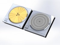
To explore SP-10 plinth designs we have created 3D CAD models of the SP-10 MkII and the SP-10R motors, and these are attached here. Technics provides drawings for both models showing the location of the mounting holes. These are mostly accurate when compared to live samples and where possible we have tried to confirm all measurements. Where you see some measurements are .5 mm different from the documentation this is where we used our measurements, not the Technics published dimensions. We measured these to the best of our ability, but did not use sophisticated tools, just calipers.
One of the biggest difficulties when trying to design a universal plinth is that the SP-10R BMC motor housing cover and motor dampener mounting flange is not flush with the bottom surface also mounting surface of the CNC machined aluminum plate (25mm) that provides the visible top surface, major structural element and mounting plate for the SP-10R. The flange of the BMC cover is about .020" Max. above the plate. This is not consistent, and .020" is the Max. You'd want to confirm for yourself, but if you cut a .020" relief the flange should be relieved.
The bottom of the SP-10R plate is CNC milled flat providing a nice surface for rigid mounting to a plinth and coupling of the plate to the plinth material below, and the SP-10R is provided with 4 more threaded mounting bolt locations than the MkII. The SP-10R also has threaded holes in the same 5 locations as the MkII. See attached a 2D DXF file showing all the mounting hole locations.
In any case, these models are provided for your own research and investigation. Happy building!
Jamie
Attachments
Ironman, thanks. One of my big questions has always been the elevations of the TT and Tonearm. I built a plinth and made a recess for the stock EPA 100 Tonearm. The stock plinth had recesses for both. But I have no idea what happens if I want to use, as an example, The Kuzma 4P. Any thoughts?
Thanks for the drawings.
Thanks for the drawings.
Using the bottom mounting plane of the motors as a reference, we estimated that the stock Technics arm board used in the Technics plinths designed for the SP-10 motors put the tonearm mounting surface about .250" above that flush mounting plane surface. Technics has a bit of a habit of not leaving much room to adjust the tonearm height lower in their stock arrangements. And, we designed explicitly for an EPA-100 which has plenty of VTA adjustment in the mounting post, plus the on the fly adjustment. So, I'm not sure off the top of my head, but I believe we planned to have the arm board surface only about 1/8" or even less above the flush mount plane of the SP-10R or SP-10 MkII. But, we also modeled the EPA-100 tonearm in 3D CAD as well explicitly for the 10R, and although some people don't want to hear it, the MkII is also a different height than the 10R. I don't know the Kuzma arm, or how it mounts, etc. If you can get a drawing or model you can use our 3D CAD models and correctly model entire assembly.Ironman, thanks. One of my big questions has always been the elevations of the TT and Tonearm. I built a plinth and made a recess for the stock EPA 100 Tonearm. The stock plinth had recesses for both. But I have no idea what happens if I want to use, as an example, The Kuzma 4P. Any thoughts?
Thanks for the drawings.

Hello folks,
I have an SP10mk2 which suffer from high speed rotation and after probing the FG coil, it's opened.
Have taken the motor off the chassis but I just can't dismantle the stator and not able to get access to the FG coil assembly.
Any tricks or special procedure to disassemble the stator? Many thanks!

I have an SP10mk2 which suffer from high speed rotation and after probing the FG coil, it's opened.
Have taken the motor off the chassis but I just can't dismantle the stator and not able to get access to the FG coil assembly.
Any tricks or special procedure to disassemble the stator? Many thanks!
Hi Mike,I'm rebuilding an SP-10 Mk2, and need the metal chassis & base/bottom cover. Any chance anyone here has one in their parts box they'd be willing to part with?
Condition not critical, as I'll likely have it powder coated. Attached is a photo of what I need.
Thanks,
Mike
View attachment 1073791
Have you considered mounting the motor separate to the electronics. A few of here have done this and the improvement is significant,
Hello folks,
I have an SP10mk2 which suffer from high speed rotation and after probing the FG coil, it's opened.
Have taken the motor off the chassis but I just can't dismantle the stator and not able to get access to the FG coil assembly.
Any tricks or special procedure to disassemble the stator? Many thanks!
I had a similar issue and found one FG wire broken so close to the FG it was not possible to repair. I ended up rewinding the FG coils.
Remove the 3 bolts holding the stator to the housing and will lift out.
De-solder the FG wires under the PCB.
Remove the 3 screws at the top of the FG
Be careful not to break the 2 magnets and the whole assembly will lift off.
I built a counter to rewind the coils and used the counter to count the number of turns on each coil. Unfortunately I lost the document I wrote when my laptop crashed so I'm doing this by memory. IIRC the coils are wound in opposite directions
Last edited:
I second this suggestion. The motor installed in a superior plinth is a fantastic sounding machine. especially if the platter mods described by warrjon are also executed. The best use for the stock SP10 chassis is a dinner gong. Ditto for the OEM platter. Take the opportunity to build a stunningly capable turntable. There are lots of posts in this thread explaining the modifications.Hi Mike,
Have you considered mounting the motor separate to the electronics. A few of here have done this and the improvement is significant,
I had a similar issue and found one FG wire broken so close to the FG it was not possible to repair. I ended up rewinding the FG coils.
Remove the 3 bolts holding the stator to the housing and will lift out.
De-solder the FG wires under the PCB.
Remove the 3 screws at the top of the FG
Be careful not to break the 2 magnets and the whole assembly will lift off.
I built a counter to rewind the coils and used the counter to count the number of turns on each coil. Unfortunately I lost the document I wrote when my laptop crashed so I'm doing this by memory. IIRC the coils are wound in opposite directions
View attachment 1073934 View attachment 1073935
I will try and report back. Thanks again.
warrjon and Bon-I second this suggestion. The motor installed in a superior plinth is a fantastic sounding machine. especially if the platter mods described by warrjon are also executed. The best use for the stock SP10 chassis is a dinner gong. Ditto for the OEM platter. Take the opportunity to build a stunningly capable turntable. There are lots of posts in this thread explaining the modifications.
Thanks for your suggestions. I'll do some more research on removing the electronics to a separate chassis. As its now set up, that shouldn't be too hard. Link to my current build.
Mike
Nice looking plinth. If you separate the electronics you will need a 12 wire umbilical cable. I found no problem using GX20 12 pin military/aviatiom/radio connectors apart from the fiddly soldering required. They sometimes come with 1-2warrjon and Bon-
Thanks for your suggestions. I'll do some more research on removing the electronics to a separate chassis. As its now set up, that shouldn't be too hard. Link to my current build.
Mike
View attachment 1074073


 m captive 12 wire cable. With my Kaneta style plinth I left the on/off switch and speed selector on the control box that also contained the power supply. It made for a cleaner look.
- Home
- Source & Line
- Analogue Source
- The Incredible Technics SP-10 Thread