I started a project to use Raspberry Zero W to control audio inputs, to turn on/off Tape2Monitor and switch Stereo to mono reproduction.
There are
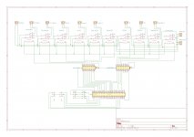
I am planning to use ten Takamisawa (Panasonic) RY5W-K relays and two ULN2003AN IC to pass control from Rasp to relays.
Software (Python) is done, all switches are working, displays are showing proper status and corresponding 3.5V from Rasp is sent to two ICs.
I have one dilemma: in order to feed 5V to specific relays (there is going to be up to 4 of them turned on at the time, one by first and up to three by second IC) can I use 5V supply from Rasp (pin 39 from schema) or should I provide additional 5V supply and connect it to pins 9 on both ICs?
Attached is a schematic and I’ll add Python script if anyone is interested.
Thanks,
Marin
There are
- Two turntable connectors (switchable by Rasp)
- Tuner
- CD/DVD
- TV/Cable
- Tape In
- Aux
I am planning to use ten Takamisawa (Panasonic) RY5W-K relays and two ULN2003AN IC to pass control from Rasp to relays.
Software (Python) is done, all switches are working, displays are showing proper status and corresponding 3.5V from Rasp is sent to two ICs.
I have one dilemma: in order to feed 5V to specific relays (there is going to be up to 4 of them turned on at the time, one by first and up to three by second IC) can I use 5V supply from Rasp (pin 39 from schema) or should I provide additional 5V supply and connect it to pins 9 on both ICs?
Attached is a schematic and I’ll add Python script if anyone is interested.
Thanks,
Marin
Attachments
Last edited:
Use an adequately rated supply, it should be able to supply Pi ands relays.
Connect your relay feed directly to the supply rather than through the Pi board if that makes sense?
I have done similar with Arduino.
Although, having looked up your relay spec, they are very low power consumption so it probably doesn't matter.
However, it is the safest way and should a faulty relay be replaced in future with a higher consumption item no harm will ensue.
Why Pi zero and not an Arduino or similar? I'm not being critical, I had similar decisions to make for a project and went for Arduino because it starts immediately and runs for a long time on battery, though I started by considering Pi zero so was curious if I'd missed anything.
You can get shift-register driver chips that would only need the SPI pins to drive, rather than 10 individual GPIO pins.
You are shorting inputs together to implement mono-mode - that will not work with low impedance sources, you'll just get horrible distortion as the sources go into current limiting. You need to passively or actively mix left and right to get mono, perhaps like this:

Can you explain the RIAA_IN1 and RIAA_OUT1 in detail, they seem rather odd.
You are shorting inputs together to implement mono-mode - that will not work with low impedance sources, you'll just get horrible distortion as the sources go into current limiting. You need to passively or actively mix left and right to get mono, perhaps like this:
Can you explain the RIAA_IN1 and RIAA_OUT1 in detail, they seem rather odd.
Why Pi zero and not an Arduino or similar? I'm not being critical, I had similar decisions to make for a project and went for Arduino because it starts immediately and runs for a long time on battery, though I started by considering Pi zero so was curious if I'd missed anything.
It is just because I am familiar with Rasp, but not with Arduino B)
You can get shift-register driver chips that would only need the SPI pins to drive, rather than 10 individual GPIO pins.
You are shorting inputs together to implement mono-mode - that will not work with low impedance sources, you'll just get horrible distortion as the sources go into current limiting. You need to passively or actively mix left and right to get mono, perhaps like this:
Can you explain the RIAA_IN1 and RIAA_OUT1 in detail, they seem rather odd.
THANKS Mark for VERY valuable input, regarding mono mode, I will adjust my schema to address it properly.
These two RIAA connectors are for phono pre (out goes as input to RIAA, in is out of RIAA pre), which is on a separate board.
It is just because I am familiar with Rasp, but not with Arduino B)
Well, you can also use the Pi as a music server.
I was surprized how cheap the Pi Zero is.
These two RIAA connectors are for phono pre (out goes as input to RIAA, in is out of RIAA pre), which is on a separate board.
You have 2 turntables?
Otherwise I'd have connected the turntable direct to the phono preamp & connected the output of that to a line level input.
Avoids switching very low level signals.
You could always use 2 phono pre-amps.
Well, you can also use the Pi as a music server.
I was surprized how cheap the Pi Zero is.
That, with Rasp 4, 8G RAM and, either BOSS or HiFiBerry, is a next project B)
You have 2 turntables?
Otherwise I'd have connected the turntable direct to the phono preamp & connected the output of that to a line level input.
Avoids switching very low level signals.
You could always use 2 phono pre-amps.
I don't yet, but that is in line with my planned sources. If I am lucky enough to make my (friend) machinist to finish a turntable (that one is dragging for years, just because we are friends and we spend more time doing other things than working in his workshop) I will have two tone arms, one with stereo and another one with mono cartridge.
I might eliminate Stereo/Mono relay and directly connect the mono source to phono pre.
- Home
- Source & Line
- Analog Line Level
- Raspberry based input selector